Progress Report for Trevor
Week 14 & 15
Date: 12/1/2023
Project Hours Since Last Report: 51
Cumulative Semester Project Hours: 219
Description of Individual Project Work Efforts:
A13a - Draft of ABET Senior Design Report
- Uploaded the template document to the team’s shared drive.
- Filled in my section.
- Assisted in filling out the team section.
Firmware
External EEPROM Driver (App/driver_eeprom.c):
- Reduced EEPROM instructions available from the driver in comparison to the basis created in week 12 given new knowledge on the team’s required use of the external EEPROM.
- Debugged both individually and with Ben by using the oscilloscope to both manually view the SPI’s output and perform automatic serial decoding on the SPI’s output.
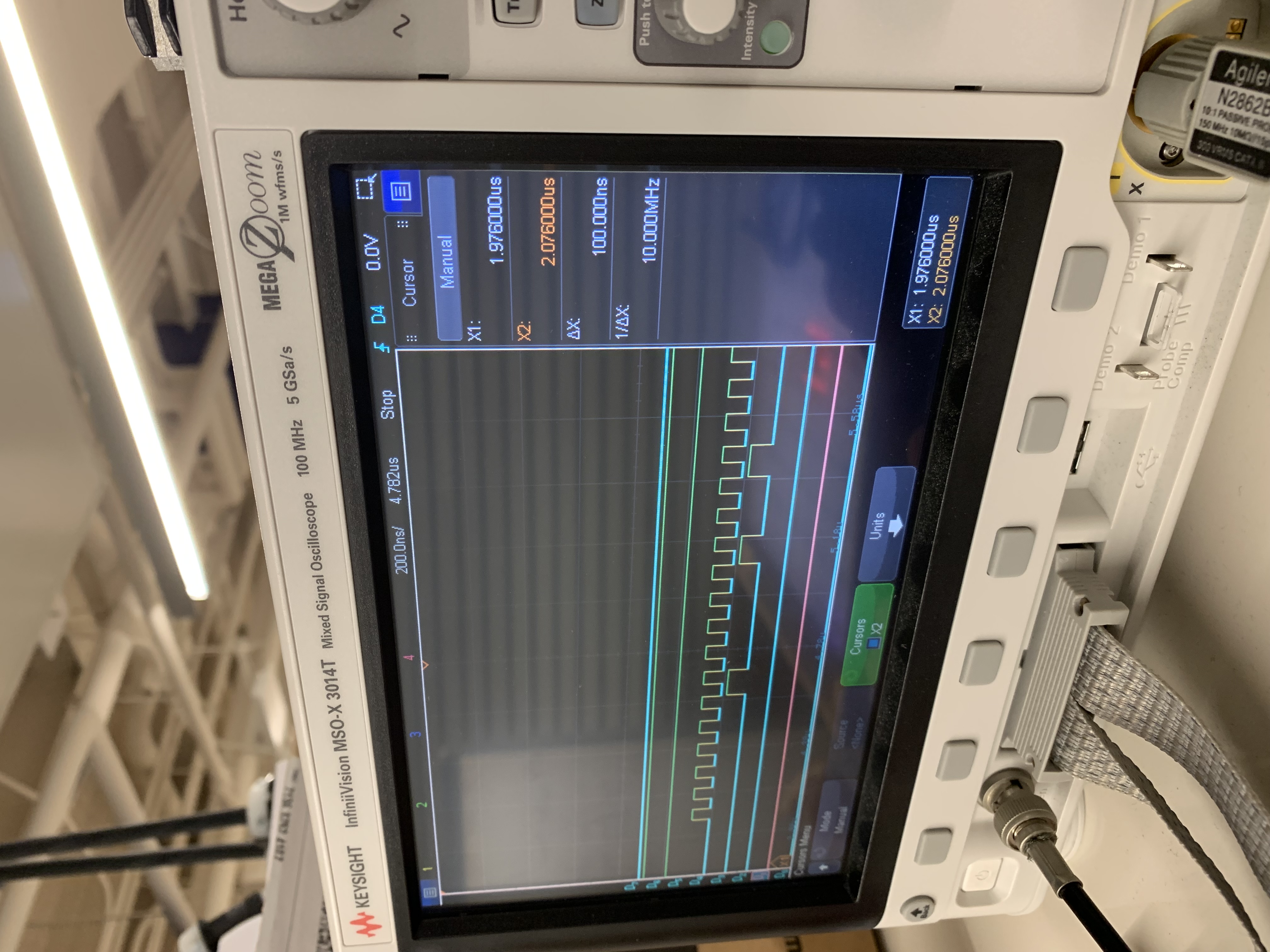
Figure 1: Oscilloscope output while debugging the external EEPROM driver (D_1 == MISO, D_2 == CS, D_3 == MOSI, D_4 = CLK).
- Implemented the driver into the overall project with the team.
State Machine (App/app_statemachine.c):
- Worked with Ben to implement each state (except for the “idle” state which was reserved for Alan and Will). A brief description of each state is below. For specifics on the state machine as a whole, see A8. The following will briefly describe how Ben and I implemented each state.
- Start: Clear menu from OLED displays, show score (“0-0”) on both OLED displays, randomly choose which player starts with the puck.
- Wait A/B: Play waiting animation, wait for the puck to be placed on that side.
- Run: Turn on centrifugal blower, display background on LEDs, display trail of puck on LEDs, check if either player scored.
- Score A/B: Immediately switch to “Win A/B” if the player has met the score requirement, otherwise play score animation before returning to “Run”.
- Win A/B: Play win animation before returning to “Idle”
- Worked with Ben to implement actions performed when switching between states. Besides re-initializing variables relating to the current state, switching between states automatically updates the table’s background LEDs, OLEDs’ display, and relay’s state when appropriate based on the previous state.
Animations:
- After filling in the state machine as described above, Ben and I created all animations required besides the idle animation. Note that each animation has an A and B variant, so each player can have a unique animation for each.
- Wait Animation: The side of the player starting with the puck blinks their color.
- Score Animation: Immediately completely color the table’s LEDs with the color of the player that scored.
- Win Animation: Slowly fill the table with the winning player’s color column-by-column starting at the winning player’s side.
Table Construction
- Added a #12x4” wood screw purchased from Menards where the length-wise support attached to each table leg. Hopefully, this will prevent the supports from warping and pulling out from the table’s leg.
- Created and installed four bus bars. The four bus bars will provide two sources of ground and two sources of 5V to the sensor PCBs, which reduces voltage drop off along the chain.
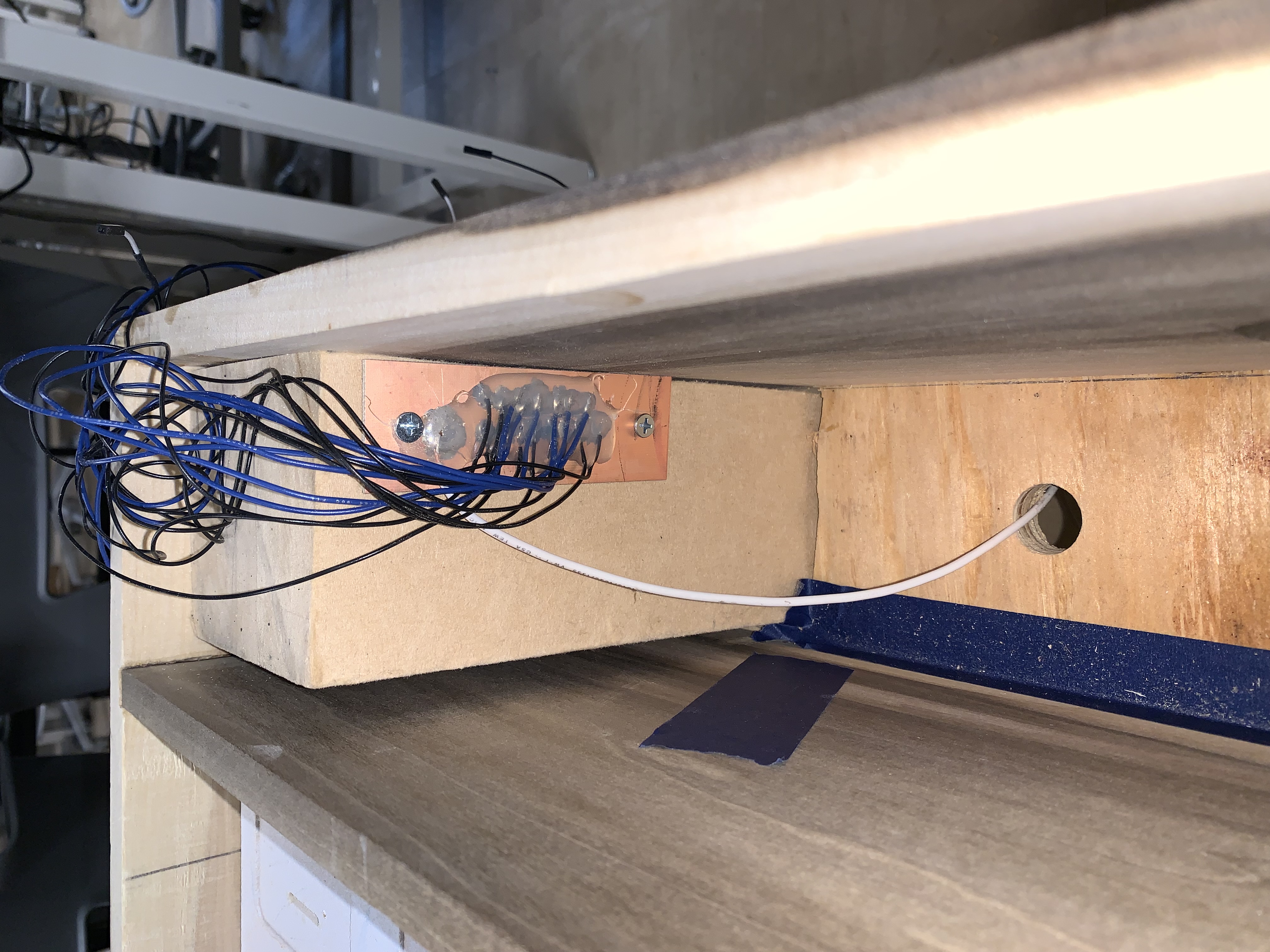
 |  |
|---|
Figure 2: On the top, an example of an installed bus bar. On the bottom-left, both installed bus bars on player B’s side of the table. On the bottom-right, both installed bus bars on Player A’s side of the table.
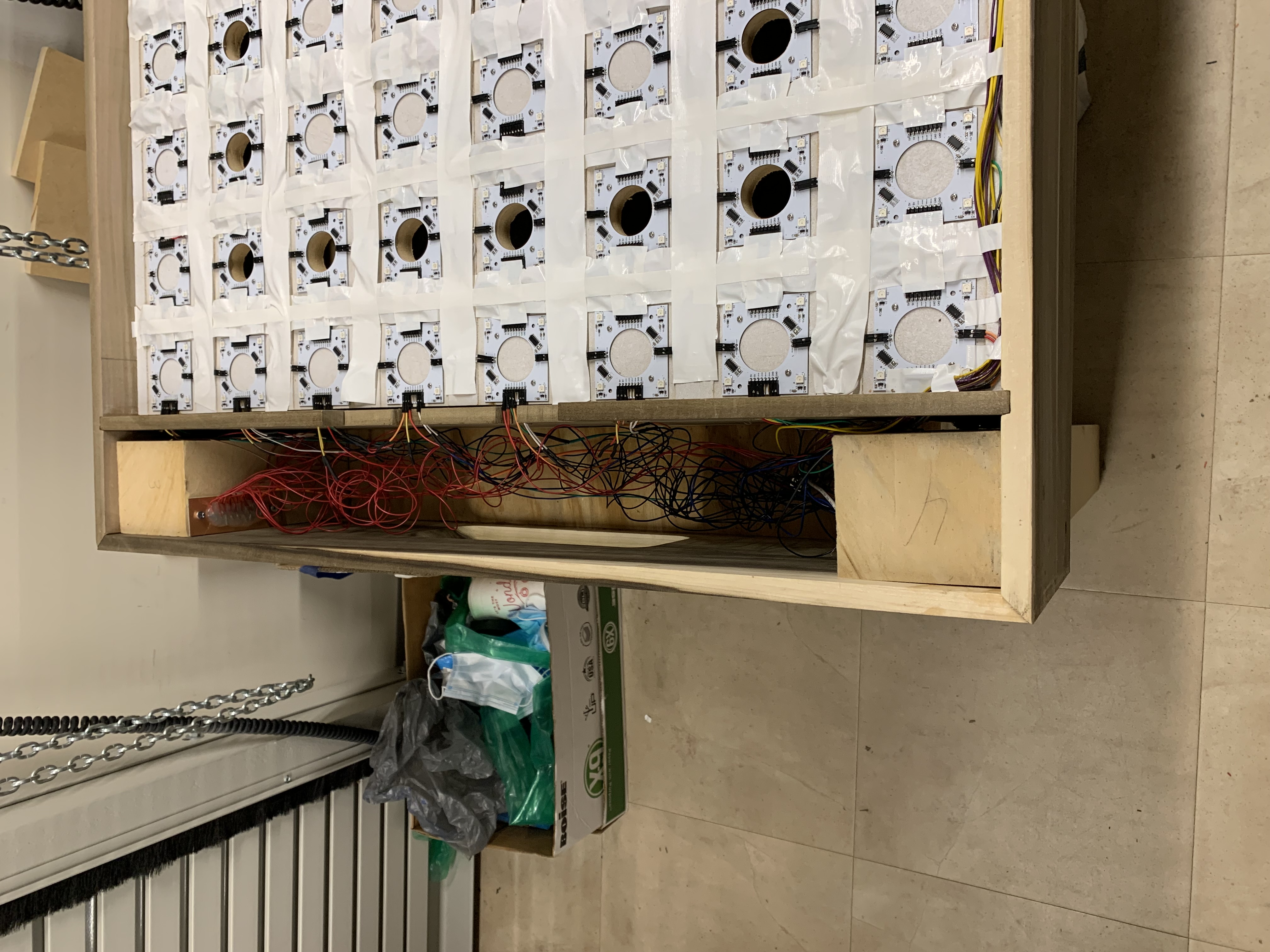
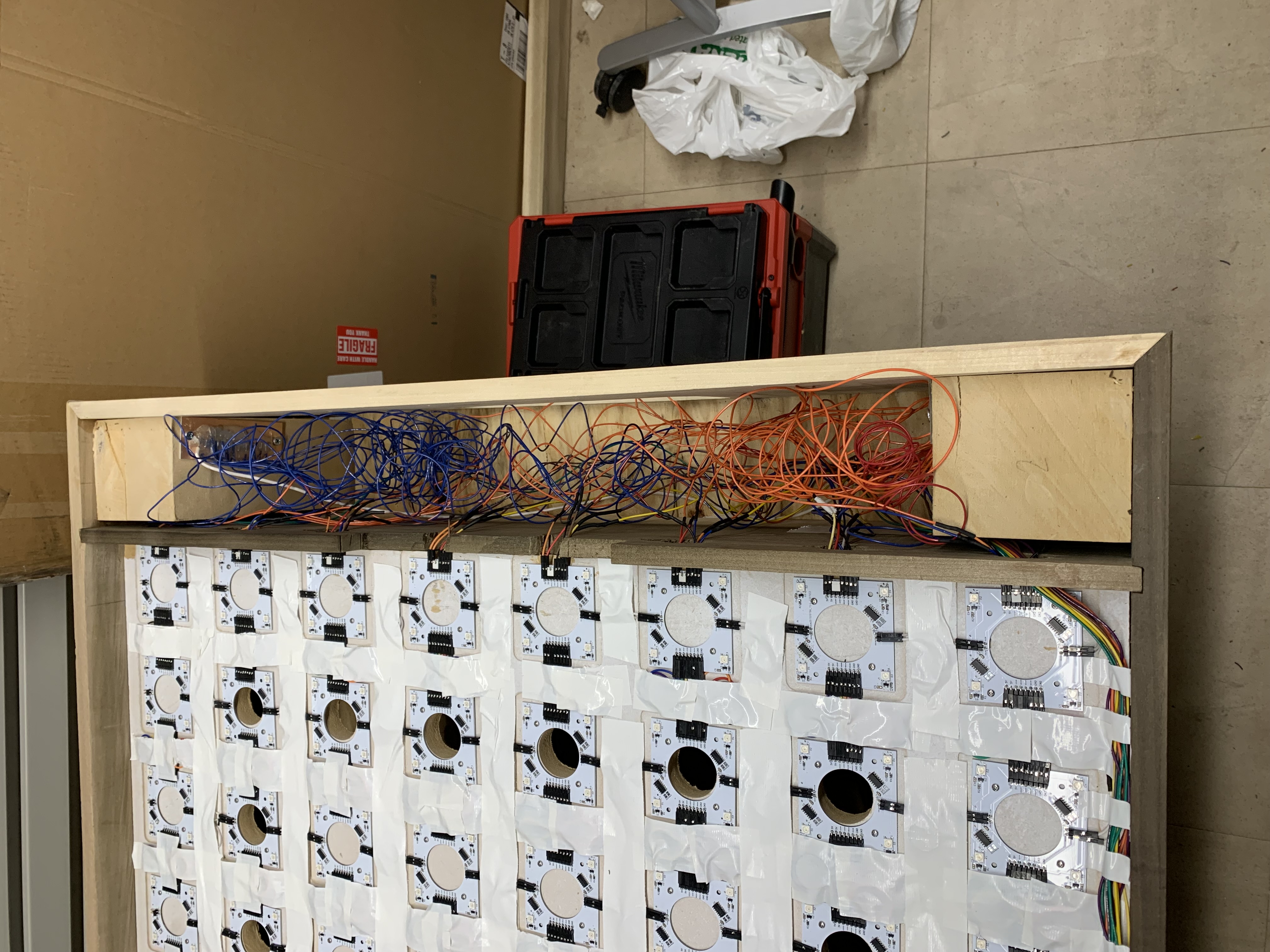
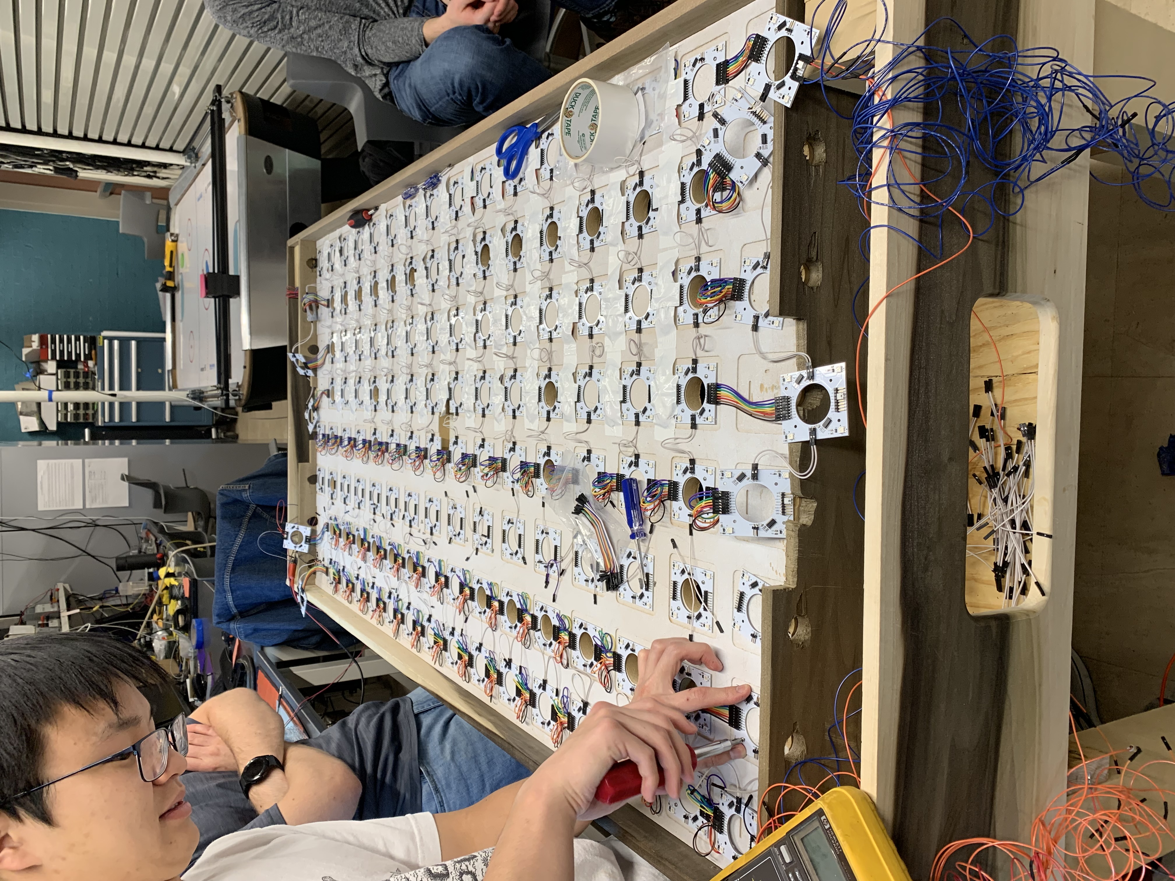
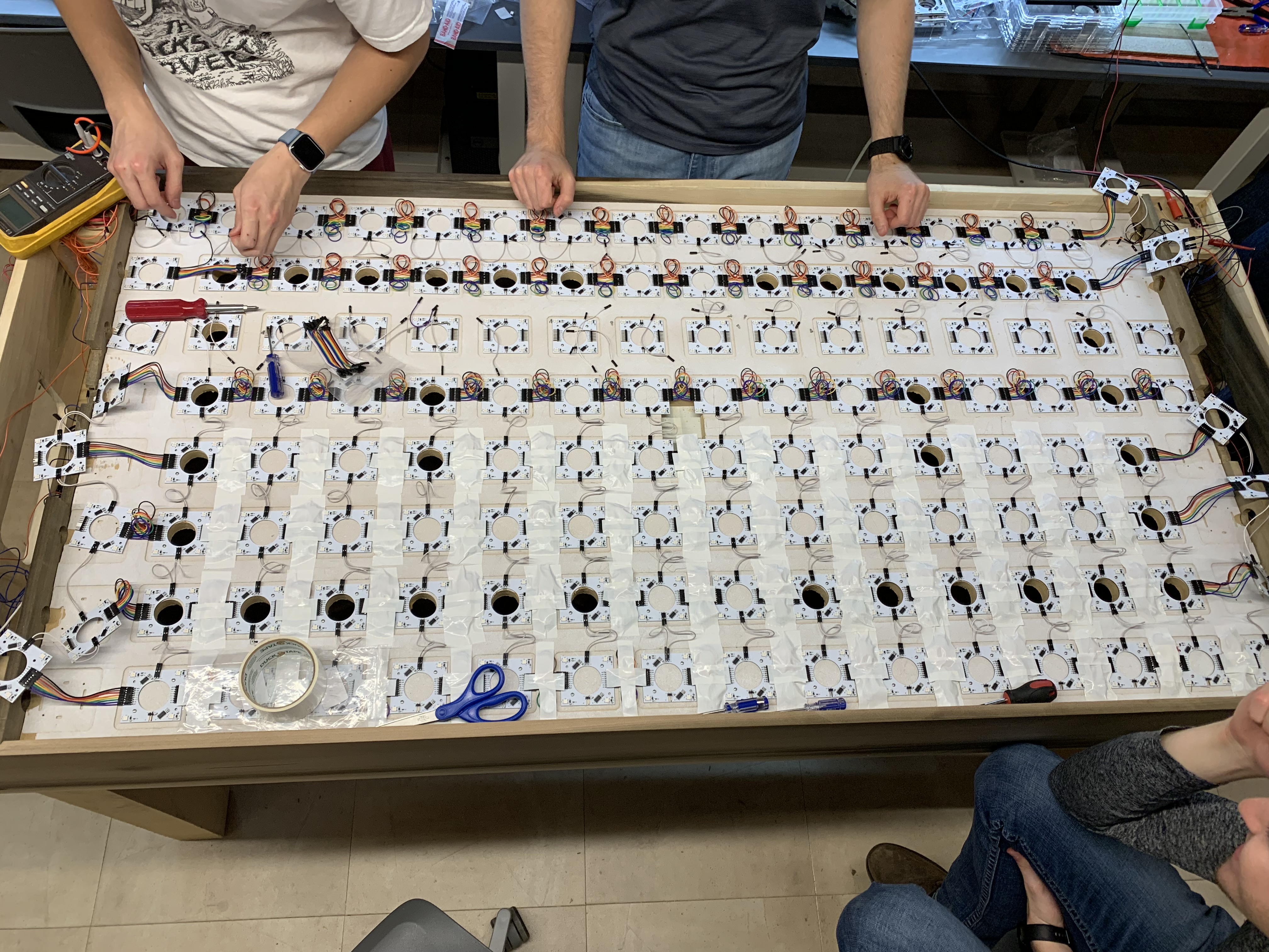
- The team worked together to painstakingly screw each sensor PCB into the MDF. Next, the sensor PCBs were wired together into rows and columns and connected to the bus bars. These wires were then twisted and taped down with white duct tape to prevent them from pushing on the acrylic or obscuring the sensor PCBs’ LEDs. Then, the compressed hall effect outputs were wired from the output edges of the sensor PCBs to the master PCB (this required creating long female-to-female DuPont wires by soldering a female DuPont wire head to both ends of a long strand of 24-gauge braided wire).
 |
|---|
 |
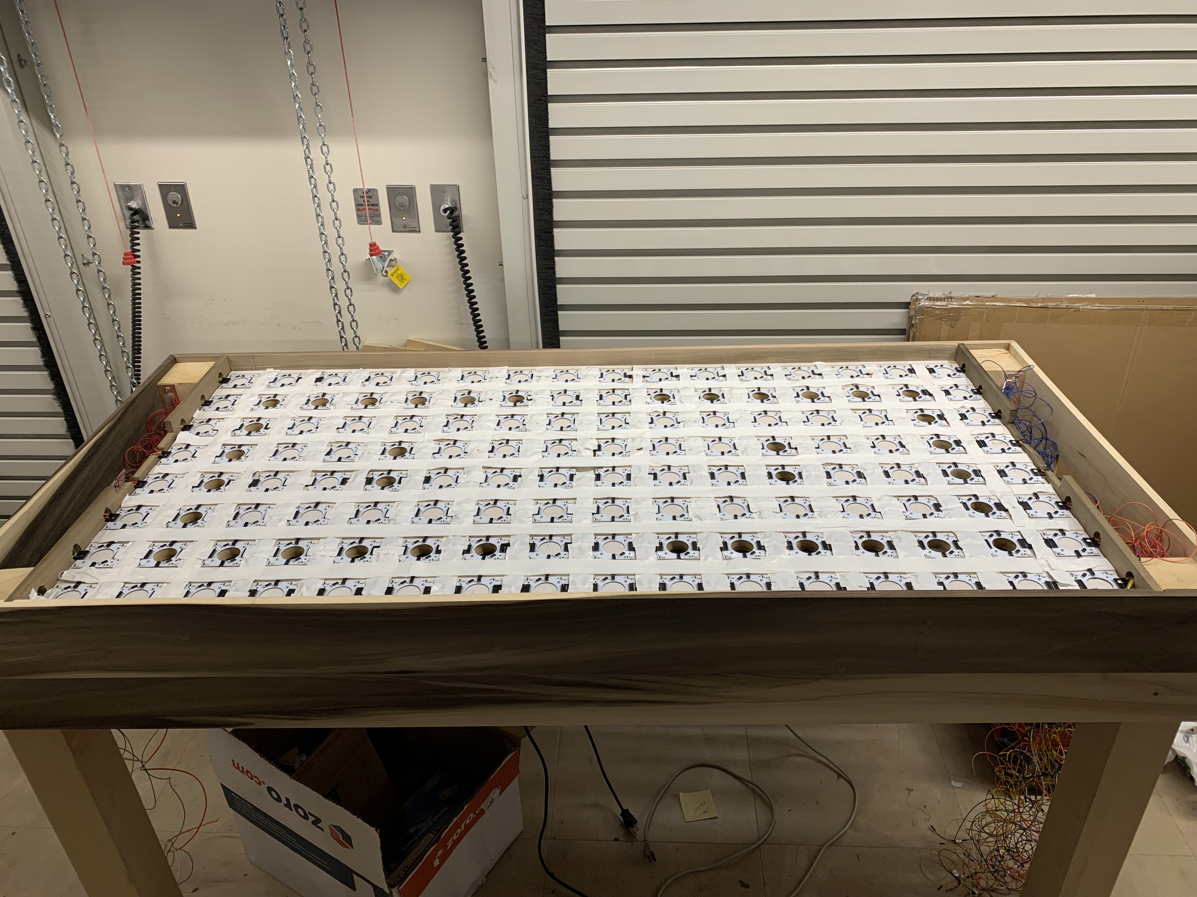 |
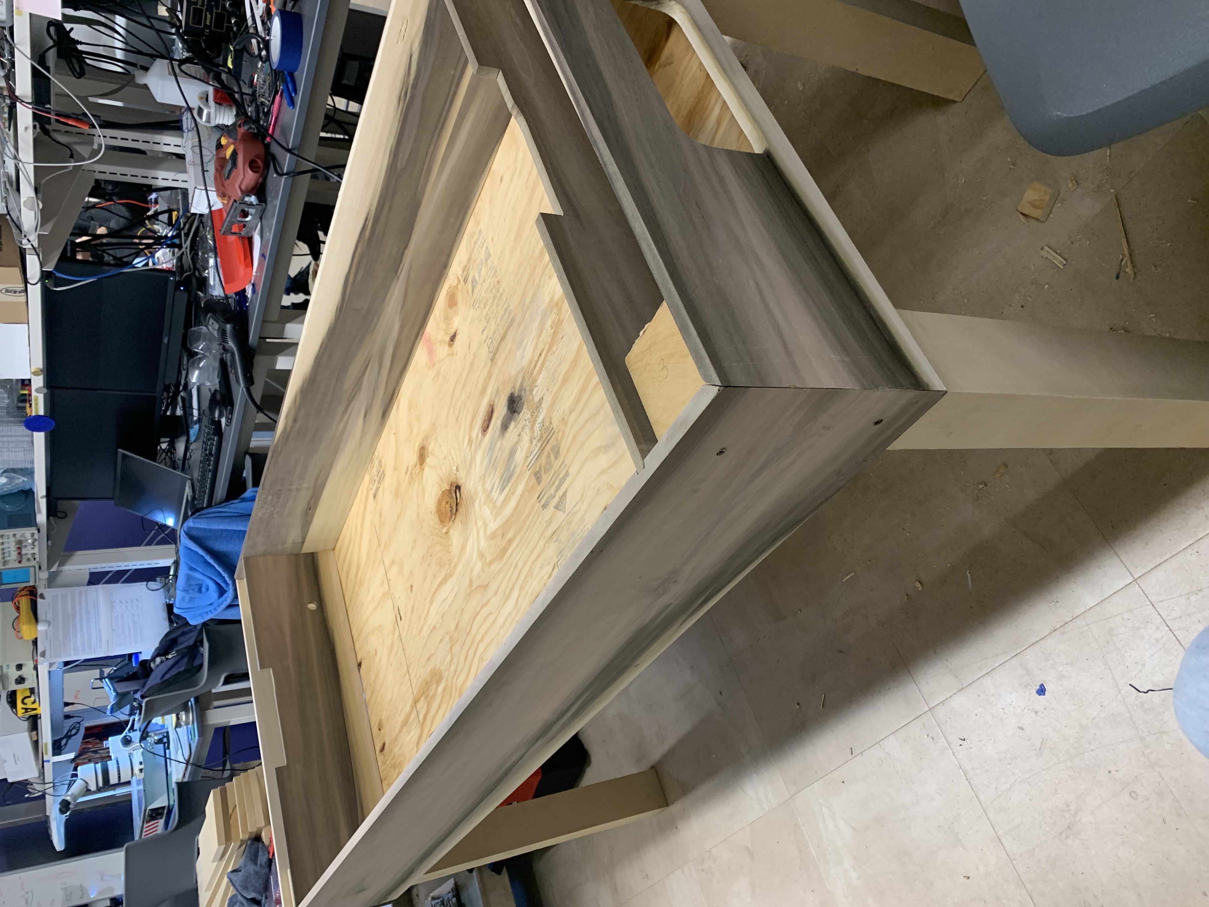
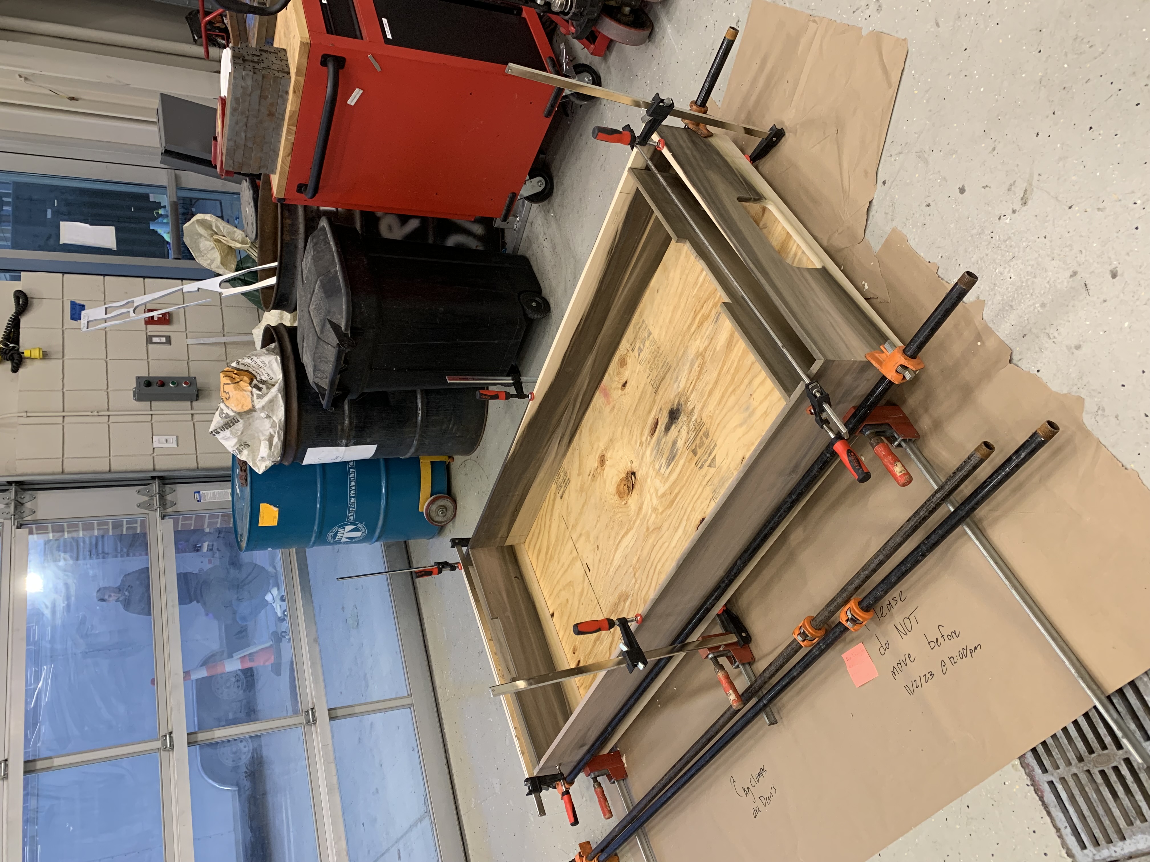
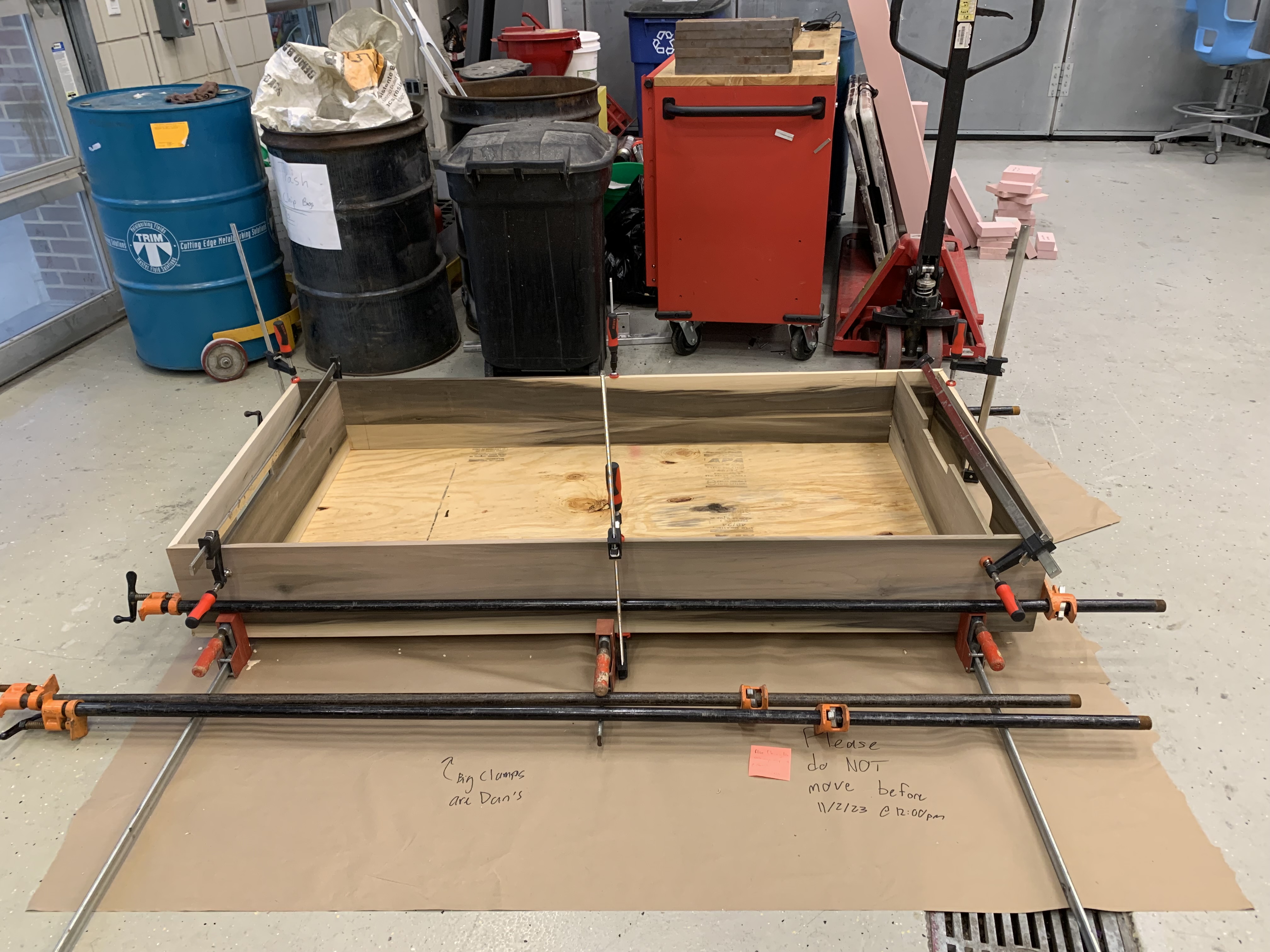
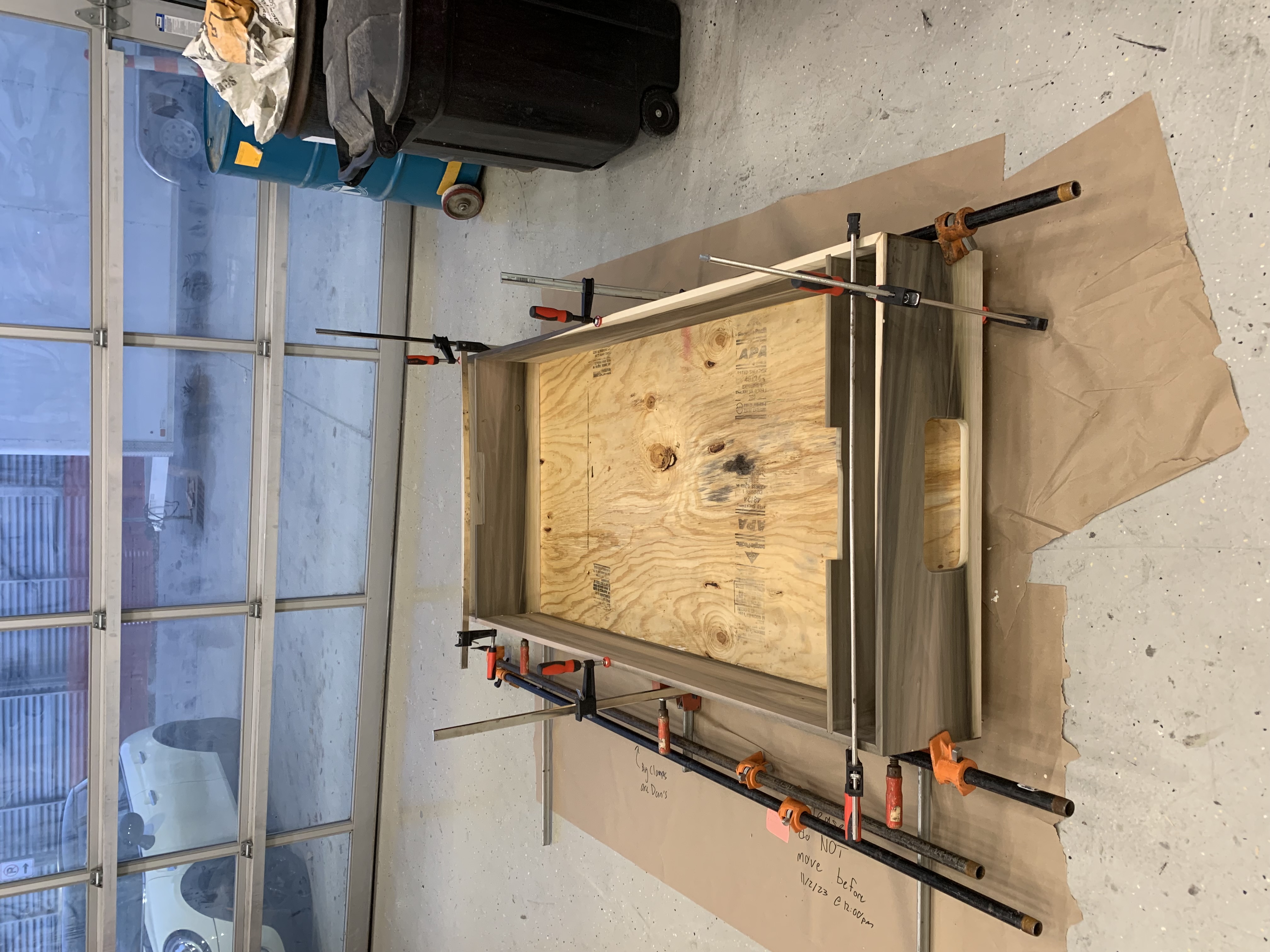
Figure 3: Snapshots of the table’s progress going chronologically from top to bottom.
- Ben and I finished constructing both ends of the table. This involved using a hot glue gun to attach two pairs of LDRs and white LEDs to each goal, using a hot glue gun to mount the goal, covering the top of the end with duct-taped cardboard, and shaping a piece of cardboard as the “puck catcher” from the goal. Note that Will cut the cardboard for us, and Alan drilled the holes into the goal for the LDR and white LED pair.
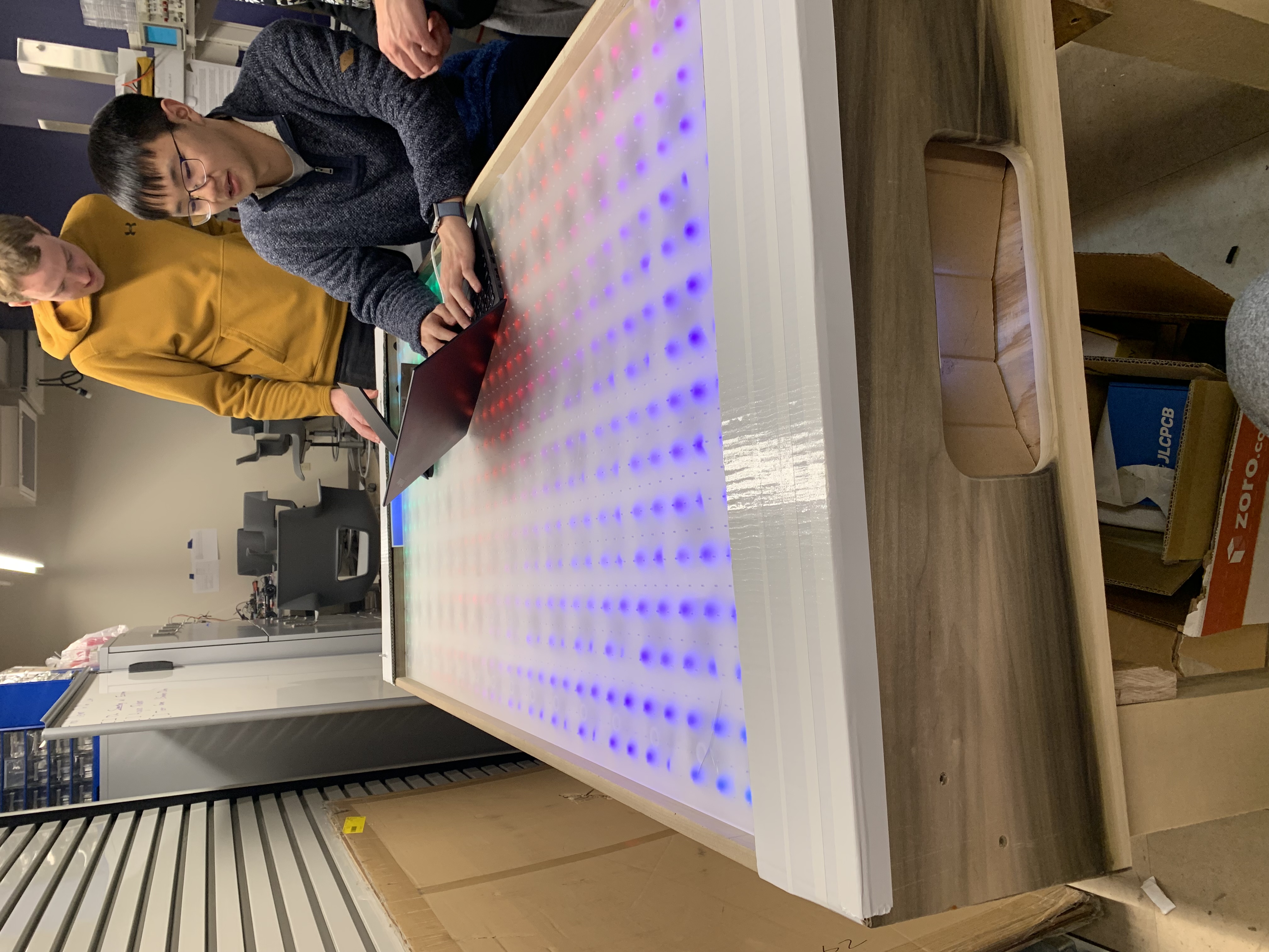
Figure 4: Table with the completed ends.
Final Project Demo
- Demonstrated the final project’s capabilities alongside the rest of the team.
Project Housekeeping
- Throughout the past two weeks, I created and loosely maintained a “Final Demo To Do List” on the team’s whiteboard.
- After the final demo, I assisted in cleaning the first level of the team’s workstation. Most lab-owned equipment has been returned and trash removed from the station. The team still needs to determine how leftover parts will be handled.
Project Media
- Throughout the past two weeks, I have been taking pictures and videos of the team’s progress. Some of these images and videos were used in our progress reports and some will appear on the team’s media page later.
Next Steps:
A13b - Final Revision of ABET Senior Design Report
- Once feedback is received, then I will revise my section and work with the team to revise the team’s section.
Final Presentation
- The team will need to create the final presentation slideshow.
- The team will need to create the demonstration video that will be used for the Spark Challenge as well.
Spark Challenge
- The team will need to create a poster for the project’s display.
- The team will need to transport the project to MSEE with the building deputy director’s assistance.
- The team will need to prepare to present the project to the Spark Challenge judges.
- The team will need to create a demonstration video that will be used for the final presentation as well.
Project Housekeeping
- Project Workstation: The team’s workstation will need to be completely cleaned before the end of the semester. This includes determining which leftover parts the team is interested in keeping and which can be donated to future senior design projects.
- Project Website: The team needs to update the team’s website. This includes adding all new project documents and uploading new media.
- Project Source: The team needs to tag the firmware used for the demonstration as a release. Then, the team can continue to add features before the Spark Challenge or clean up the repository.
- Project Future: The team needs to determine what change, if any, will be made to the project before Spark Challenge. The team also needs to determine what happens to the table after Spark Challenge.
Week 13
Date: 11/17/2023
Project Hours Since Last Report: 14
Cumulative Semester Project Hours: 168
Description of Individual Project Work Efforts:
A11 - Ethical and Environmental Analysis
- I completed and submitted the professional analysis.
Table Construction
- Ben and I cut a hole for the output of the centrifugal blower, then mounted the blower and power relay.
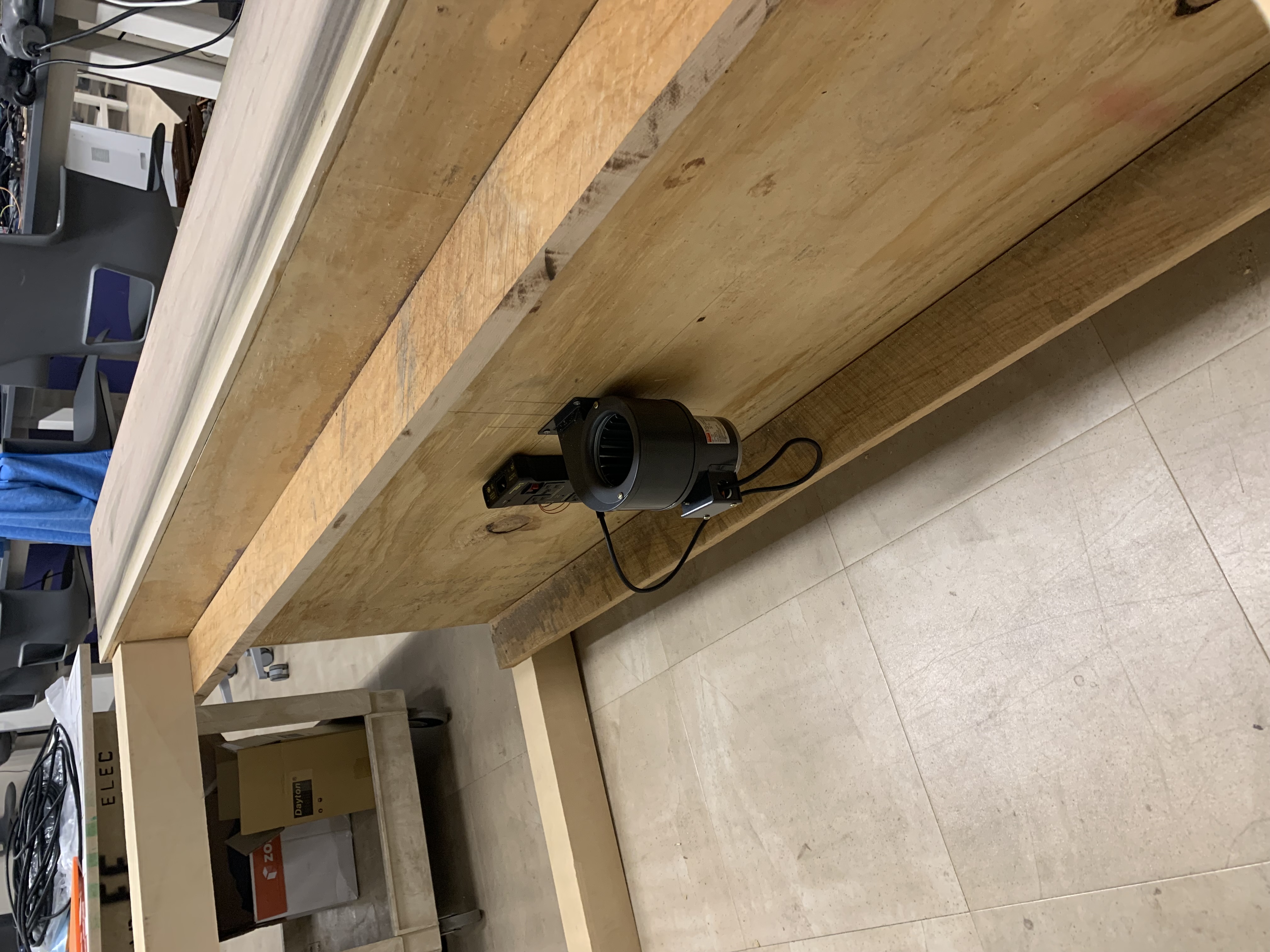
Figure 1: The mounted blower and power relay.
- During ManLab, the team learned the MDF that holds the sensor PCBs was an inch longer than the table’s cavity. Therefore, we carried the board to the basement of EE to get the edges cut, then sanded the edges till it fit.
- During ManLab, I reviewed Will’s second goal design and recommended that he drop the bottom of the output chute and increase the lip to match the table. This advice will hopefully make the puck easier to retrieve and less likely to tumble out of the table.
- Joined Alan and Ben after they had started cutting the acrylic using the CNC gantry. While the acrylic was being cut, I cut two 2.5”x6.5” MDF supports with a vertical band saw for the air chamber connecting the centrifugal blower’s output to the MDF that holds the sensor PCBs. After that I waited for the acrylic to be cut beside Ben, then helped him carry the cut acrylic and MDF supports back to lab.
Figure 2: A short video showing the acrylic being cut on the CNC gantry.
- One of the mounted length-wise support boards under the table ended up twisting, which pulled out the majority of one of the screws. To remedy this, I removed and remounted the twisted support while also adding two width-wise support boards (which Alan cut to length from the spare wood Ben and I had claimed) under the table to help prevent the support from re-warping.
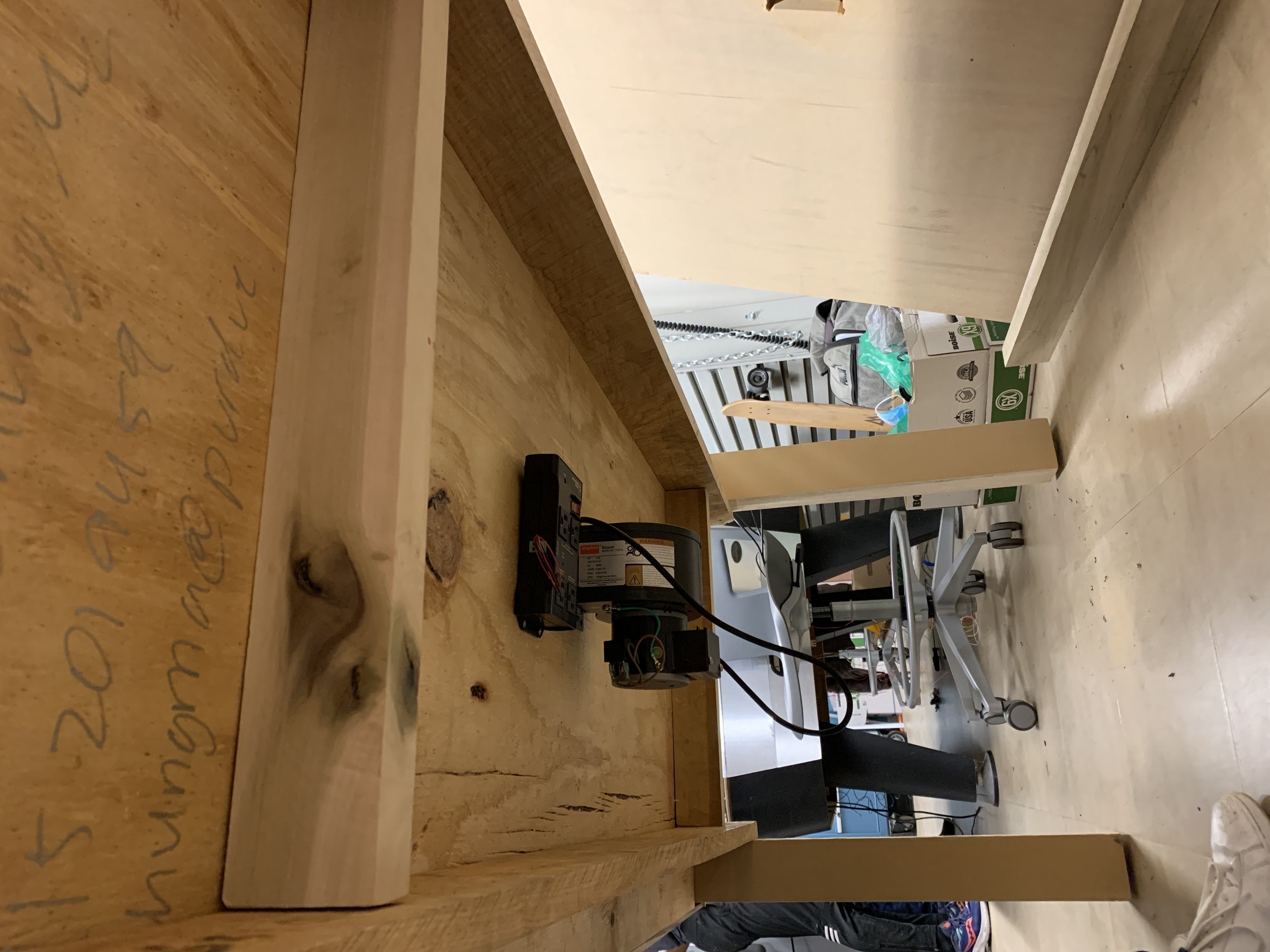
Figure 3: The added width-wise supports and the remounted length-wise support (on the right).
- I went shopping at Menards for materials that would be needed as the team continued to construct the Smart Air Hockey Table. I bought six #12x4” wood screws, a 6”x18” felt blanket, white duct tape, and GE gaps & cracks foam. The screws will be used to better mount the length-wise support boards to the soft table legs, which will hopefully prevent more warping. The felt will be used for the bottoms of the 3D printed pushers. The white duct tape and GE gaps & cracks foam will be used to help make the Smart Air Hockey Table airtight for better air pressure out of the game surface. While dropping the materials off at lab, I took some pictures of the 3D printed goal for Will’s progress report.
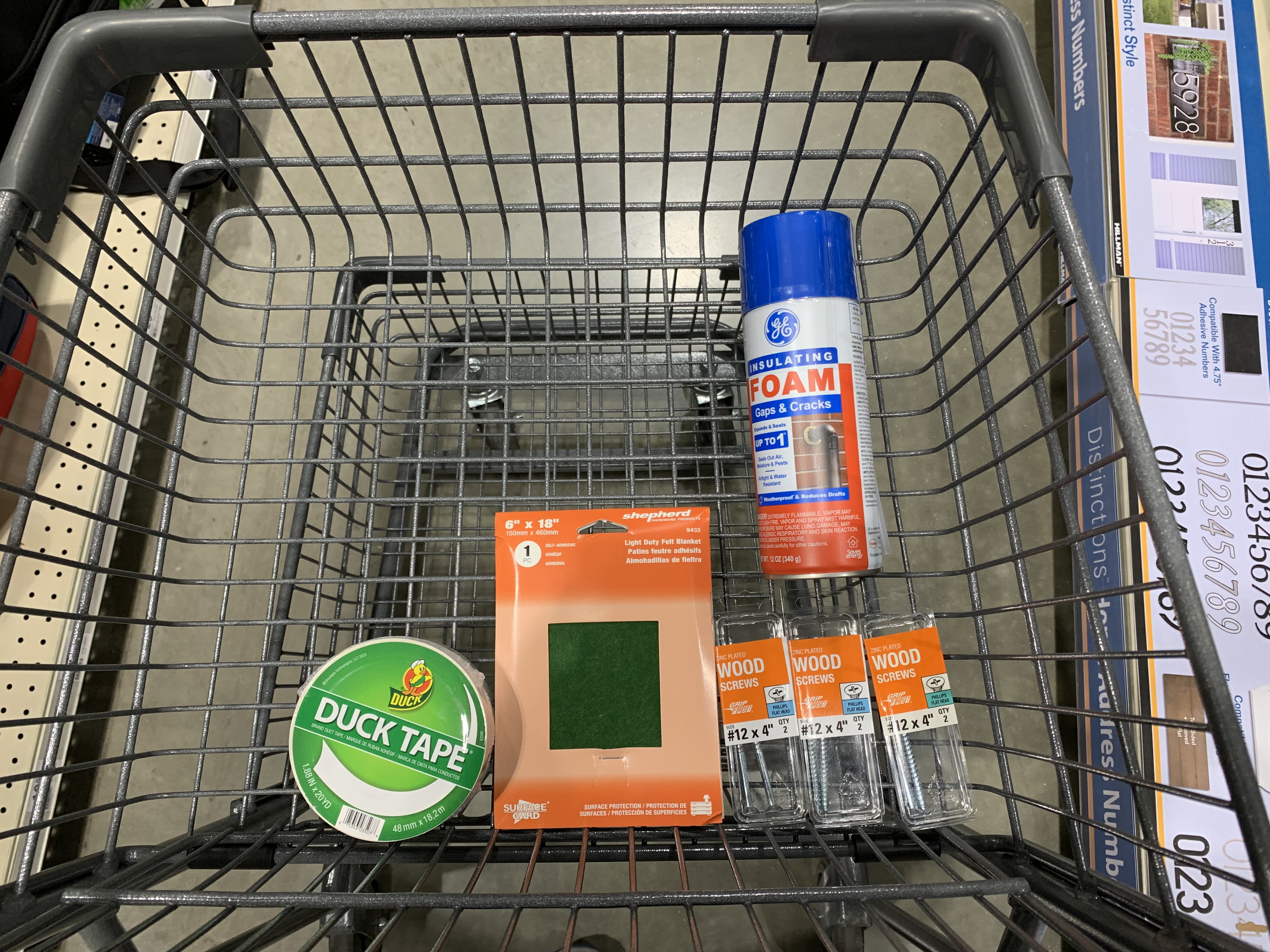
Figure 4: The full purchase.
Next Steps:
Table Construction
- Most immediately, the team needs to assemble the playing surface, which includes permanently mounting the MDF supports, the MDF which holds the sensor PCBs, the acrylic supports, and the acrylic playing surface. As of the end of this week, the prerequisite parts have been produced, so this is just a matter of assembly.
- The table still needs a goal feeder mechanism which can house the white LED and LDR pair.
- The table still needs covers above the goal mechanism with OLEDs embedded to house the wiring and other components underneath. The team has been discussing potentially making the cover removable to provide serviceability to those components.
- As table construction continues, the team will soon be able to install various components, such as the power supply, the power relay, the master PCB, etc.
External EEPROM Driver
- There has been no progress on the external EEPROM driver as the team has been completely focused on constructing the Smart Air Hockey Table. Ben and I plan on resuming work once the table has been sufficiently constructed or over Thanksgiving break, whichever comes first.
- For details on what needs to be done, see the “Next Steps” section of my week 12 progress report.
Week 12
Date: 11/10/2023
Project Hours Since Last Report: 25
Cumulative Semester Project Hours: 154
Description of Individual Project Work Efforts:
Testing & Preliminary PSDR Checkoffs
- I created a basic test for the debug LEDs which toggled the debug LEDs every 100 milliseconds. In addition to testing the debug LEDs, this test was also used to test that the microcontroller was being programmed properly.
- I created a test for the hall effect sensor inputs which mapped each of the four hall effect sensors of a sensor PCB to a debug LED. (Associated with PSDR #1)
- I created a test for the LDR inputs which mapped each of the four LDR inputs to a debug LED. (Associated with PSDR #2)
- I created a test for the OLED displays which simply displayed Will’s font test to all connected displays. (Associated with PSDR #3)
- I created a test for the encoder switch and rotation. Pressing the encoder’s switch toggled a debug LED. The “selected” debug LED could be changed by rotating the encoder while the debug LED is on. (Associated with one of the stretch PSDRs)
Figure 1: A short example of the encoder test showing the “selected” debug LED changing as the encoder is rotated.
- During testing the individual components as we assembled more of the master PCB, an issue was discovered concerning programming and resetting the microcontroller. The microcontroller occasionally would not run the code programmed to it using the ST-LINK v2. Using the on-board reset button would sometimes work and other times cause the microcontroller to become unresponsive. However, holding the reset button for several seconds before releasing would cause the microcontroller to properly reset every time. Power cycling the microcontroller by manually turning off then back on the power supply acted similarly, but we also noticed that reducing the length of the wire connecting the master PCB to the power supply increased the chances the master PCB would work properly after power cycling. After Ben and I heuristically discovered these issues as well as performing several voltage measurements at key points, we hypothesized that there was interference in the signal which caused the undesired behavior. To test this theory and potentially rectify the issue, Ben continued assembling the master PCB by adding the decoupling capacitors. After adding the decoupling capacitors, the problem completely disappeared with the microcontroller working properly 100% of the time after being programmed, reset, or power cycled.
- During testing the hall effect sensors, we discovered an issue within the hall effect driver. Some of the bit shift operations being performed to combine the various inputs were incorrect. The fix for this was simple as we could utilize STM32CubeIDE’s debugger to view the variable stored the combined inputs as we tested each input individually. If the variable did not change how we expected, then we would recalculate and fix the respective bit shift operation.
- During testing the LDR inputs, we discovered an issue within the goal detection driver. The pins used as inputs for LDRs were different between the nucleo used for prototyping and the master PCB since the nucleo used a larger chip package. The fix for this was extremely simple since Ben and I designed the driver to use the pins defined at the top of the file, which allows for it to be easily reconfigured.
- On 11/7, Ben and I were able to demonstrate four of the PSDRs for their preliminary checkoffs. Thus, all five of the project’s PSDRs have received their preliminary checkoffs.
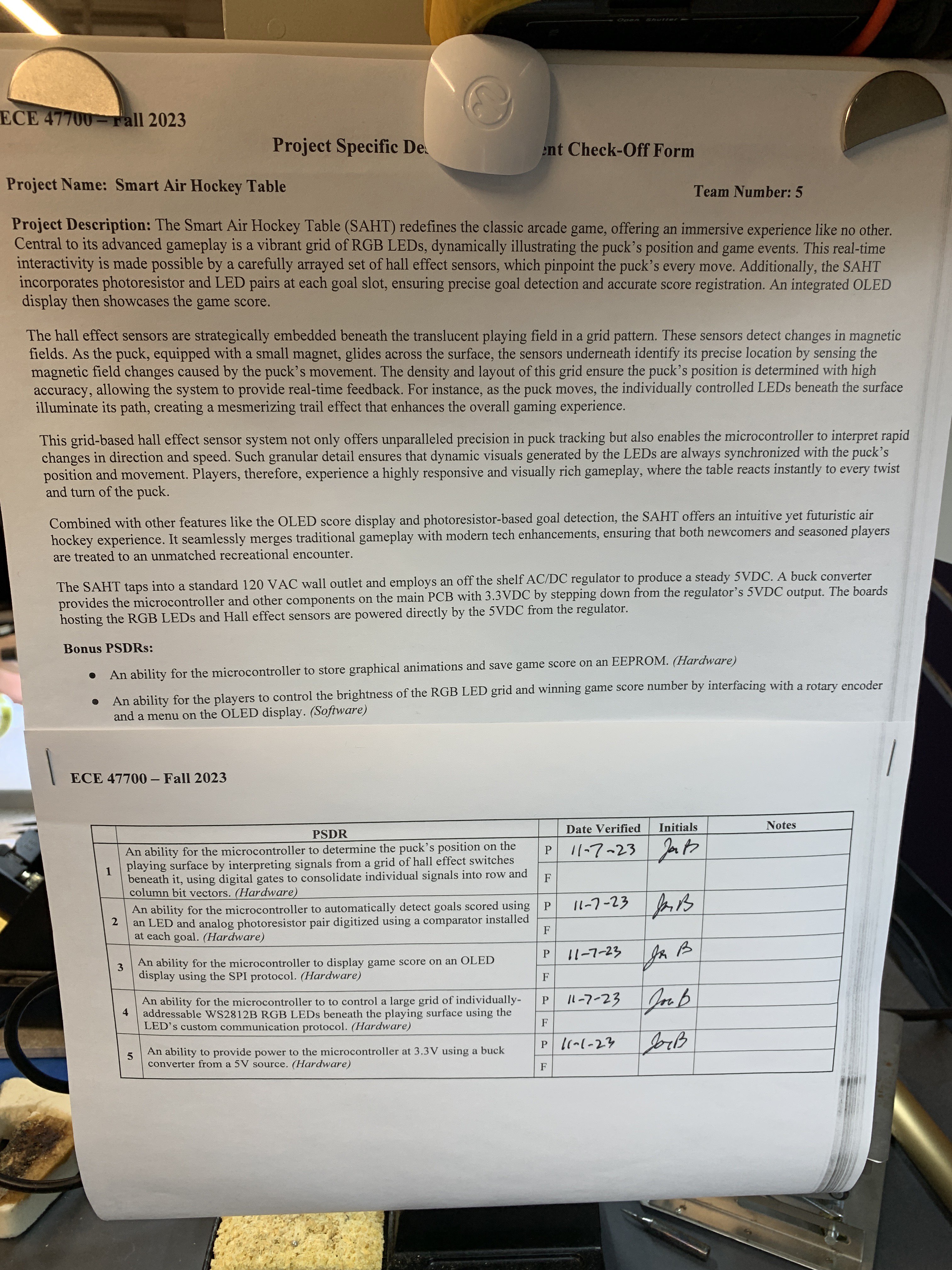
Figure 2: The team’s PSDR checkoff sheet with all preliminary PSDR checkoffs being completed.
Table Construction
- Ben and I used white primer to roughly coat the top of the MDF. The team intends for this to make the table look more cohesive under the frosted acrylic when the Smart Air Hockey Table is turned off. Given that this is an aesthetic concern of a prototype, the imperfect result is acceptable.
- Alongside Ben, I went to BIDC to look at the available scrap wood to see if any were viable for creating legs for the table. Later that day, Ben and I showed Will the pictures we took of potentially viable pieces of scrap wood to use. We collectively determined which was the best candidate, which Will and I then went to claim.
- I reserved a time slot at BIDC for cutting the table’s legs out of the scrap wood and cutting supports to place under the MDF using leftover MDF. The MDF supports will also create the central air chamber transferring the airflow from the air blower attached to the bottom of the table to the MDF.
- Ben, Will, and I worked together to cut the legs and MDF supports at BIDC under TA supervision. The legs were cut using a vertical band saw and the MDF supports were cut using a table saw.
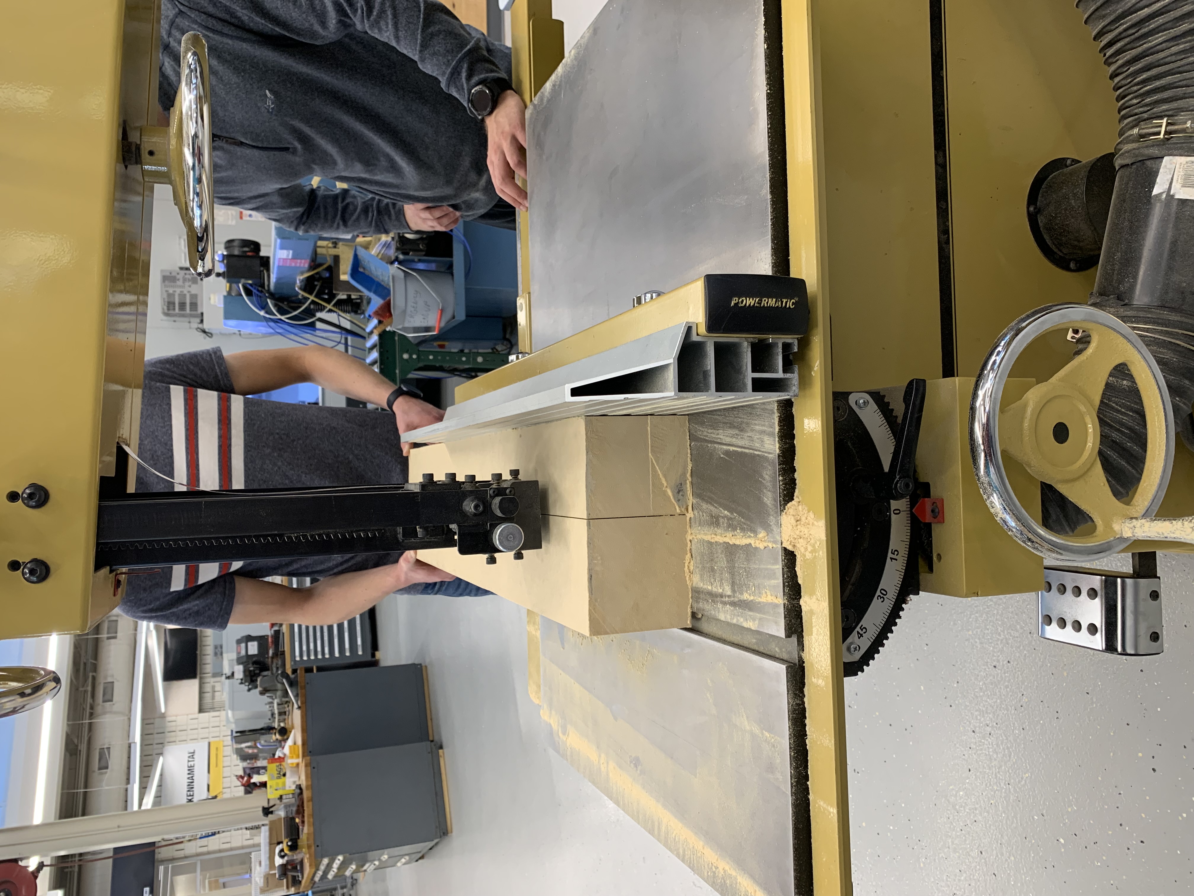
Figure 3: One of the legs being cut using the vertical band saw.
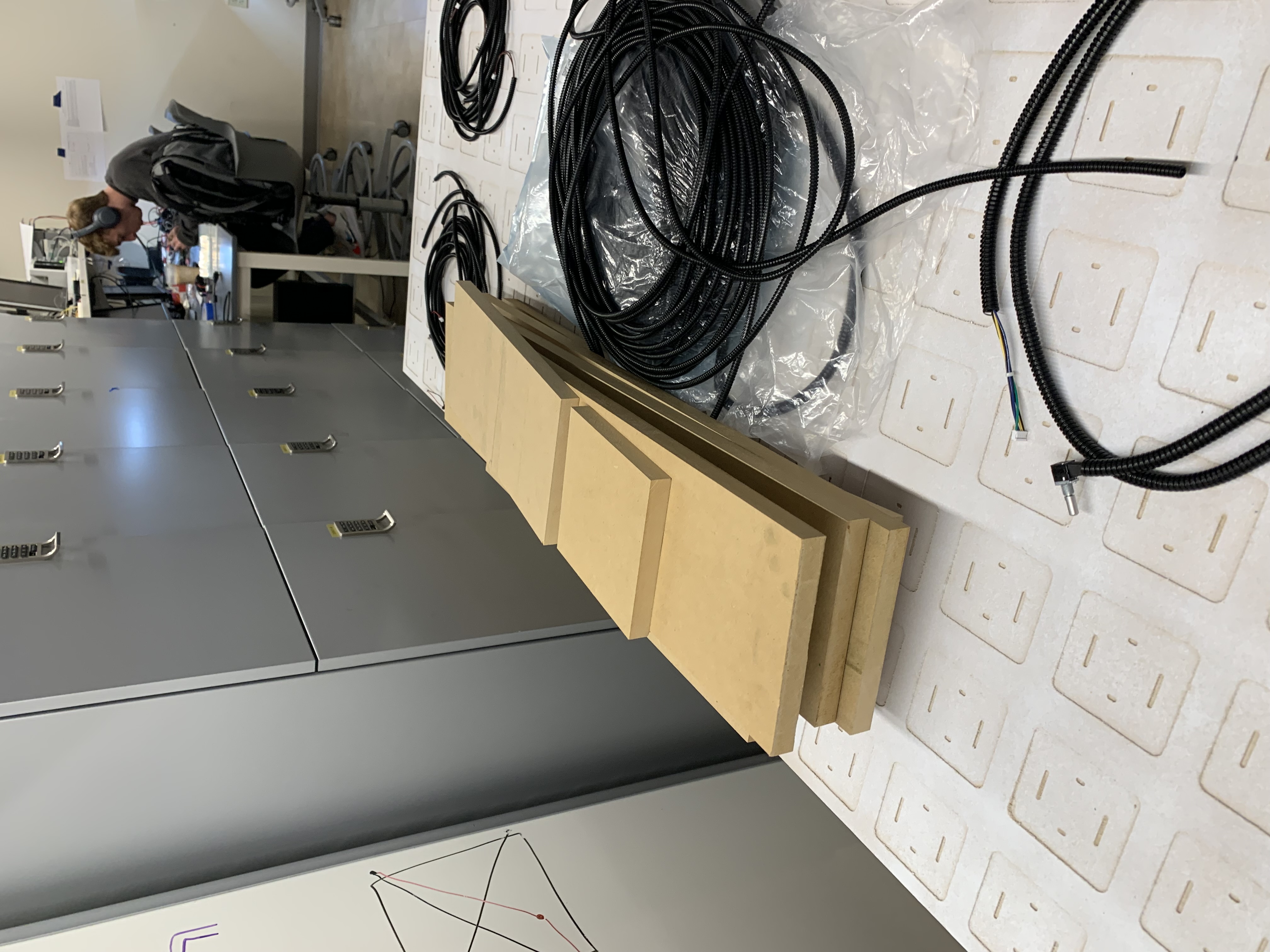
Figure 4: The MDF supports stacked in lab after being cut to size at BIDC.
- Ben, Will, and I attached the legs to the table.
 |  |
|---|
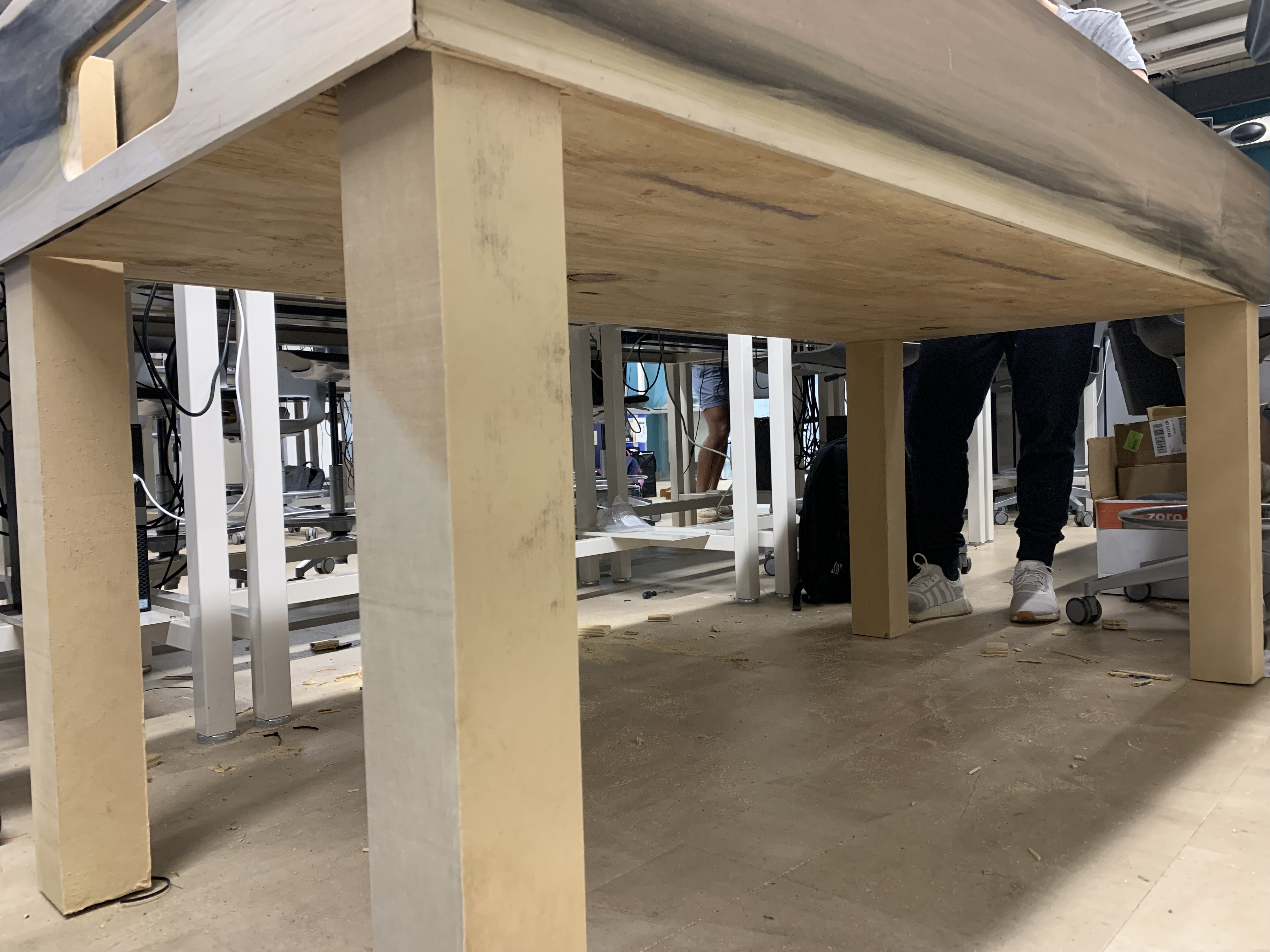
Figure 5: On the left, the table with legs from a top, isometric view. On the right, the table with legs from a bottom, isometric view.
- Ben and I claimed scrap wood from BIDC for bracing under the table. The planks going length-wise across the table was split in half width-wise using a table saw then trimmed length wise using a hand saw. Ben and I have installed the length-wise braces, but the width-wise braces will wait until after we have determined where to install the components under the table. This namely includes the blower, power relay, and master PCB.
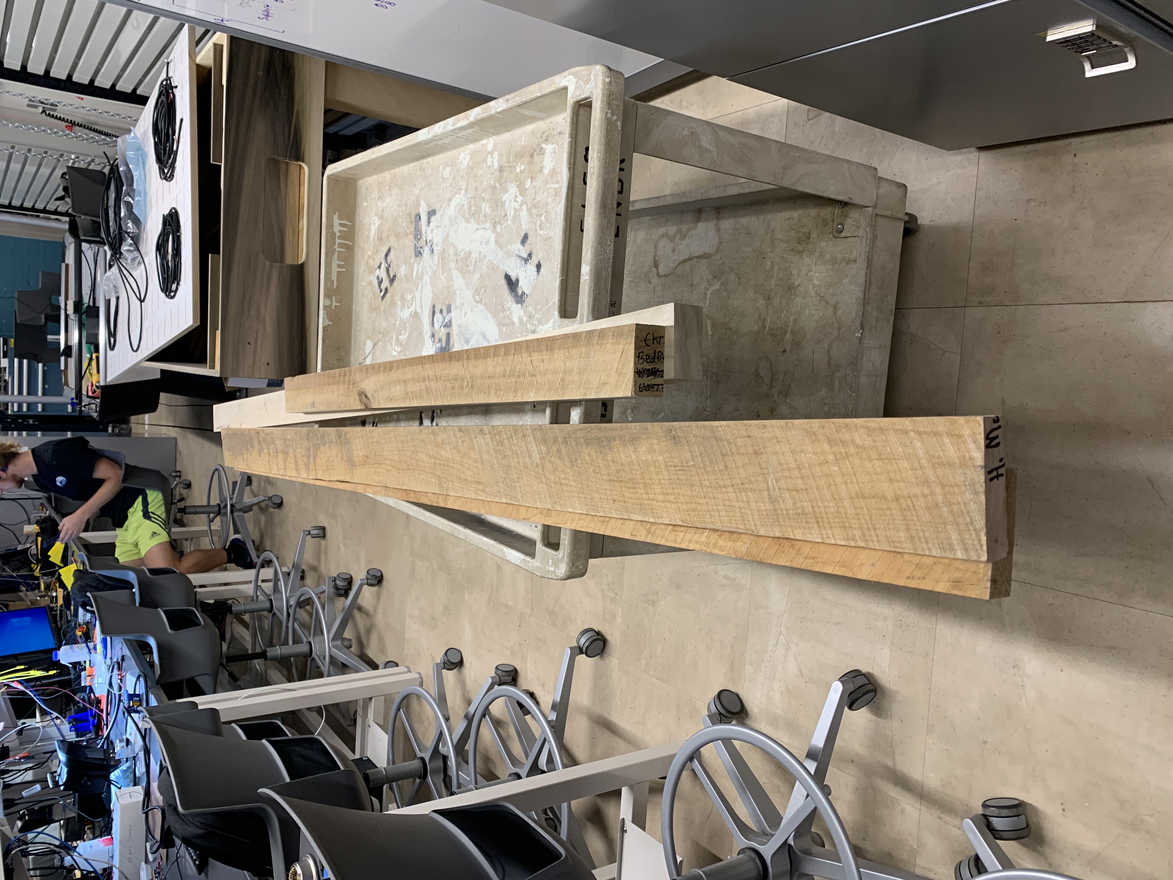
Figure 6: The planks that will be used for the length-wise and width-wise braces under the table.
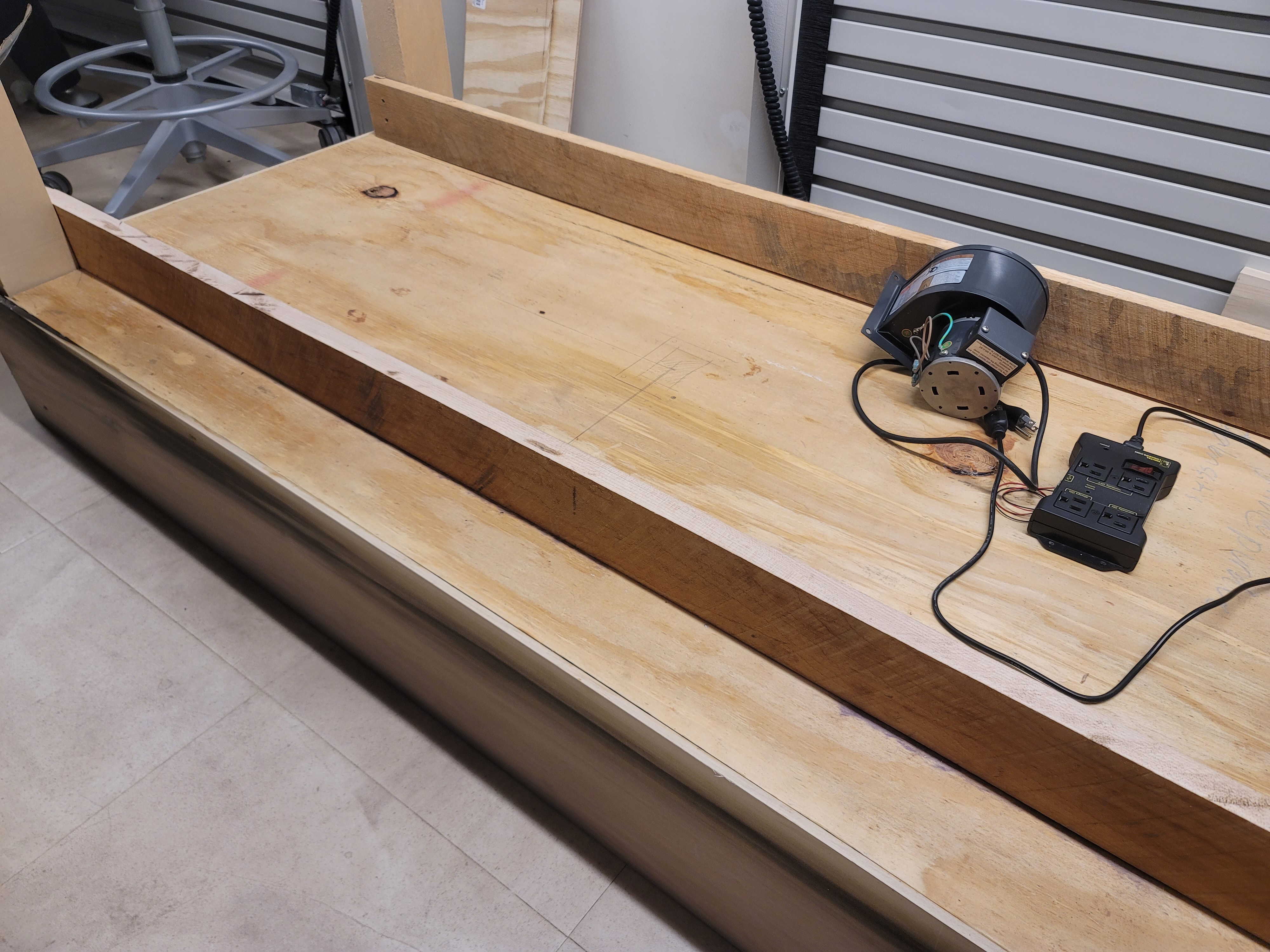
Figure 7: The table (upside down) with the length-wise braces installed.
External EEPROM Driver
- I created a basis for the external EEPROM driver, which Ben and I can test and work off of. The basis includes creating basic helper functions, an initialization function, and functions calling individual EEPROM instructions.
In-Progress Header File & In-Progress Source File
A11 - Ethical and Environmental Analysis
- I am responsible for performing the ethical and environmental analysis of the Smart Air Hockey Table for the team.
- I have created a rough draft of the document organizing topics to discuss for the ethical and environmental analysis.
- The environmental analysis is almost completed.
Project Housekeeping
- Ben, Will, and I cleaned off the team’s lab tables of the clutter that accumulated over the course of electrical assembly.
- I submitted my Qualtrics form to register the Smart Air Hockey Table for the Spark Challenge.
Next Steps:
Table Construction
- As mentioned previously, the team still needs to install the MDF supports which will also create the air chamber. In addition, a hole will need to be cut within this air chamber to mount the air blower to.
- As mentioned previously, the team needs to determine where each component will mounted beneath the table. After this is determined, then the width-wise braces can be installed either before or after mounting those components.
- The table still needs a goal feeder mechanism which can house the white LED and LDR pair.
- The table still needs covers above the goal mechanism with OLEDs embedded to house the wiring and other components underneath. The team has been discussing potentially making the cover removable to provide serviceability to those components.
- As table construction continues, the team will soon be able to install various components, such as the power supply, the power relay, the master PCB, etc.
External EEPROM Driver
- As mentioned previously, Ben and I will need to test the basis that I have created. After testing the basis of the driver, Ben and I can focus on developing the specific EEPROM functionality required by the project to meet our stretch PSDR. Most notably, the project will need to be able to save and load persistent user data and load animation frames. In addition, the driver should provide a way for programming the EEPROM with the animation frames, although this functionality will only be used in a companion program for initially programming the EEPROM.
A11 - Ethical and Environmental Analysis
- I need to complete the environmental analysis then begin and complete the ethical analysis.
Week 11
Date: 11/03/2023
Project Hours Since Last Report: 11
Cumulative Semester Project Hours: 129
Description of Individual Project Work Efforts:
JLCPCB Order
- On 10/31/2023, the team’s JLCPCB order, placed by Ben, was received.
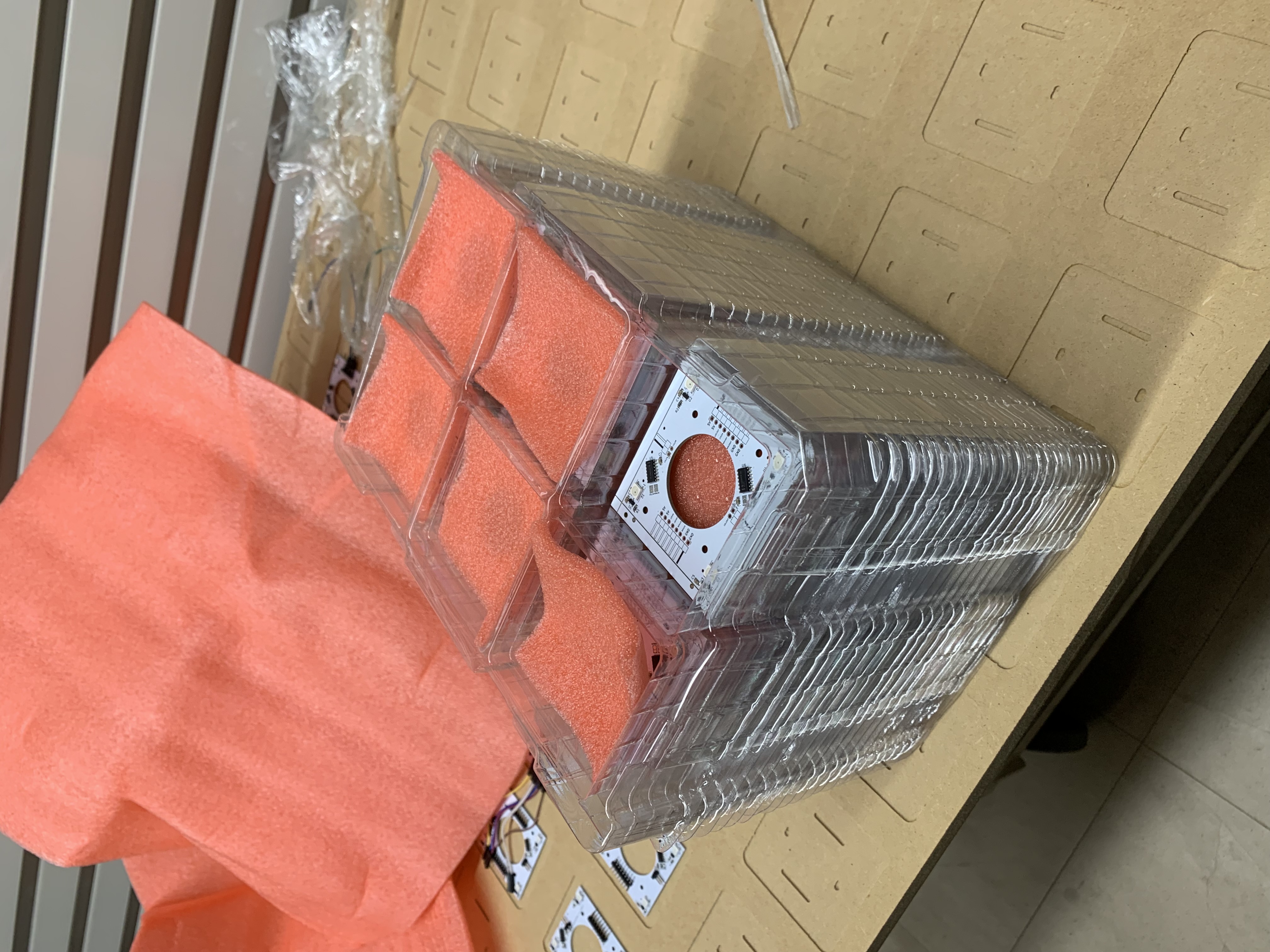
Figure 1: The stack of sensor PCB as received from JLCPCB.
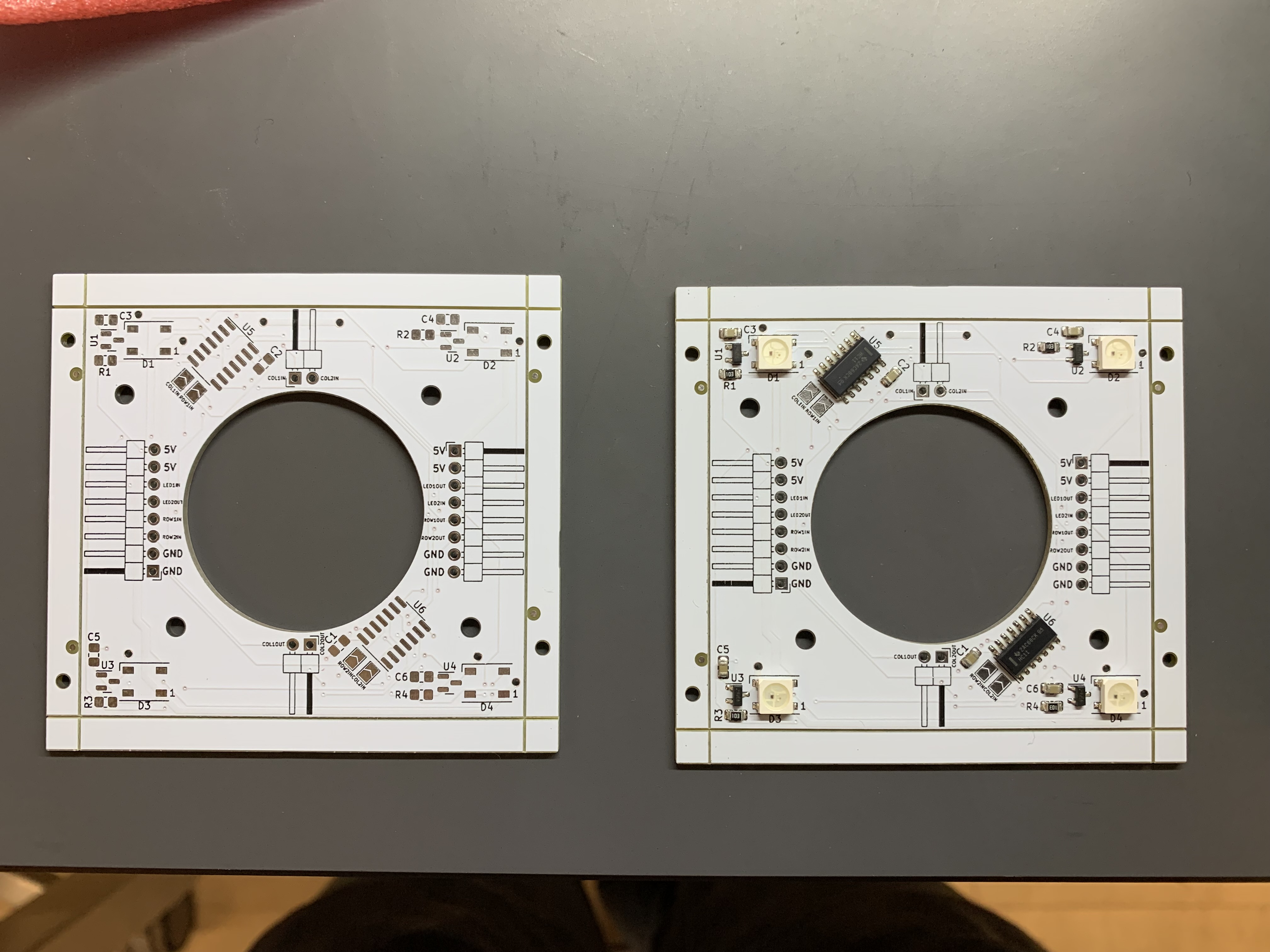
Figure 2: On the left, a bare sensor PCB. On the right, a JLCPCB assembled sensor PCB (without the THT components, AKA the pin headers).
- Ben and I snapped the v-scores off the assembled sensor PCBs and placed them on the MDF. The top row and leftmost column have the solder jump pads configured properly for their position.
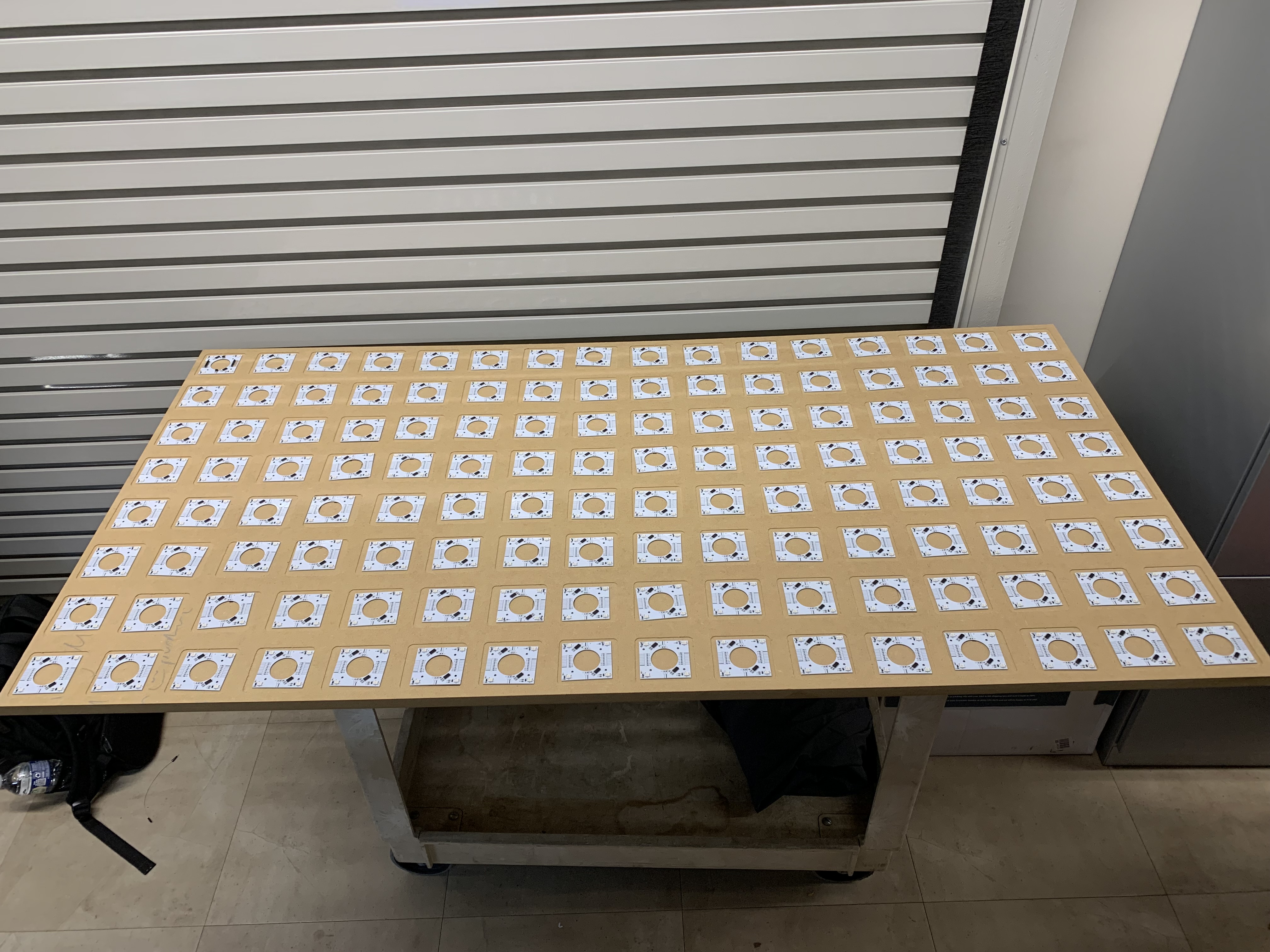
Figure 3: The MDF filled with JLCPCB assembled sensor PCBs. Note that the sensor PCBs are not installed.
- Besides this initial progress, the other team members have primarily been working with this grid so I will leave describing the progress made on that front to my other team members.
DigiKey Order
- While a single order was placed with DigiKey on (as described in the previous progress report), DigiKey had an internal error that resulted in the delivery being separated into two packages.
- The first package was received on 10/31/2023 and was brought to the lab the same day.
- However, by 10/31/2023, the second package’s tracking information stated that it had not been received by FedEx. Thus, I notified DigiKey of the issue and the package was received on 11/03/2023 and was brought to the lab the same day.
- There were some minor delays in the assembly of the rev B master PCB due to the second package being delayed; primarily due to missing the inductor required for the buck converter.
Table Construction
- Worked alongside Alan to glue the main body of the air hockey table together.
- The individual pieces were previously fabricated by Alan and Will. However, some pieces required additional shaping so they would fit together properly.
Figure 4: A timelapse of Alan and I gluing the air hockey table’s main body together.
 |  |  |
|---|
Figure 5: Various views of the air hockey table’s main body drying.
- After leaving the table in the bay to dry (with BIDC staff’s permission), Will and I transported the main body of the air hockey table to the lab as further work will only require small tools. Furthermore, the lab provides better access as the team will not need to reserve time slots at BIDC.
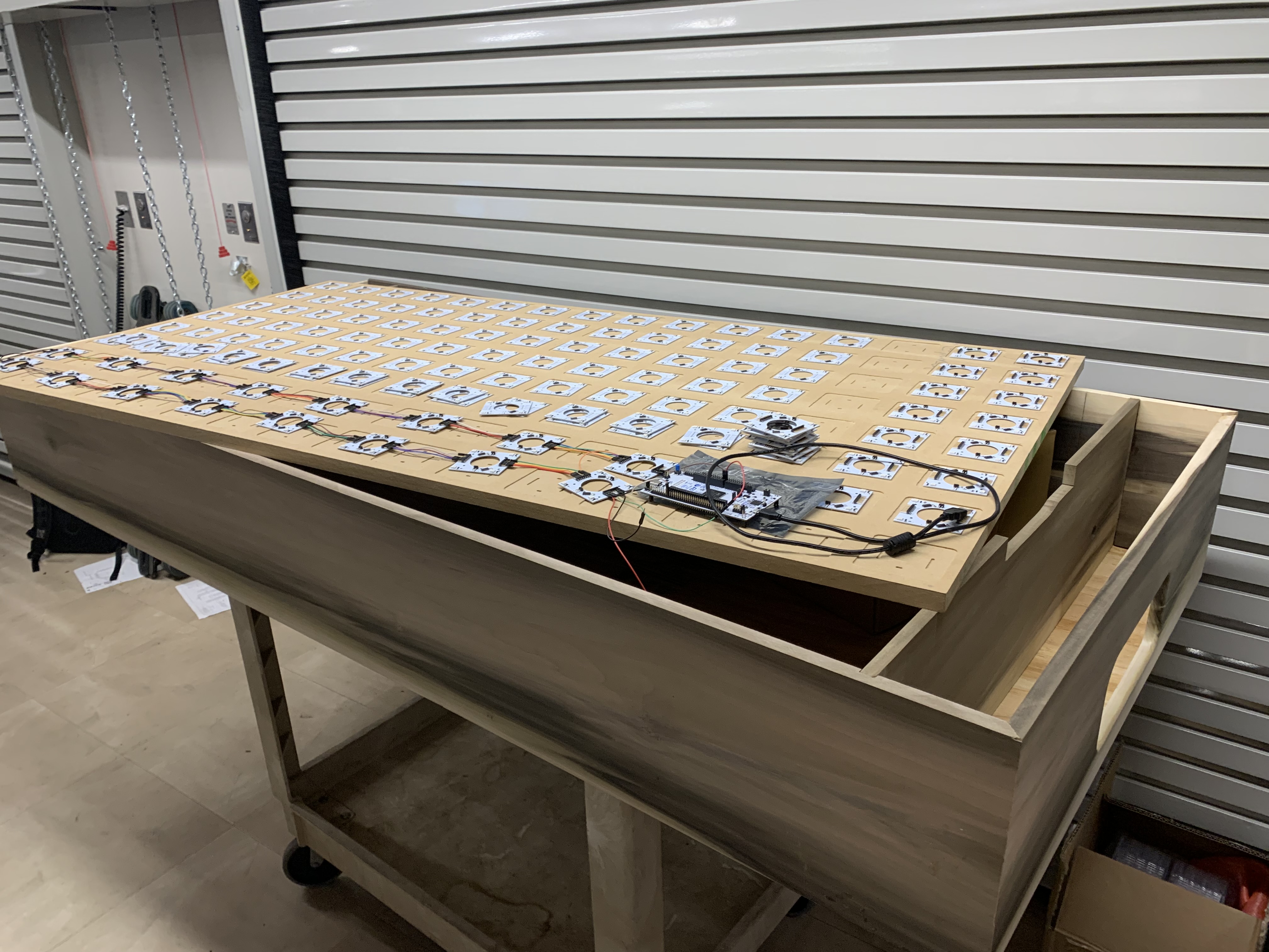
Figure 6: The air hockey table’s main body in the ECE477 lab.
Firmware
- The focus on completing this stage of the air hockey table’s construction before Alan’s absence combined with the DigiKey delivery issue has resulted in development on the external EEPROM driver effectively being effectively delayed. While there has been some discussion between Ben and I on how to implement the external EEPROM driver, we have been hesitant to continue development given our inability to test since the rev B master PCB could not be assembled. While the rev B master PCB can now be assembled, Ben and I have decided to pause development on the external EEPROM driver until the preliminary PSDR checks have been completed with the rev B master PCB.
Next Steps:
Table Construction
- Now that the main body of the air hockey table is at our lab station, progress on the packaging of the air hockey table should increase.
- As stated before, Alan is still the team member in charge of the air hockey table’s construction, and I will assist him when possible.
- However, Alan will be absent for a significant portion of this upcoming week due to traveling for a conference. The team has yet to decide whether we will pause construction on the table while Alan is absent. This will be determined based on how long it takes to complete the firmware tasks described below.
Firmware
Preliminary PSDR Checkoffs:
- Despite all the project’s primary PSDRs being defined as hardware PSDRs, each requires integrating the microcontroller (except for the PSDR #5). Thus, a simple program provides the easiest way of proving that our project meets the PSDRs requirements for a preliminary checkoff.
- While Ben assembles each component of the rev B master PCB, I will create a demonstration program for each preliminary PSDR checkoff. These demonstration programs may use the team’s previously developed drivers when necessary, though I will attempt to keep the programs as simple as possible.
External EEPROM Driver:
- As stated previously, Ben and I still plan to develop the external EEPROM driver together. However, this will be delayed until the team has completed all the preliminary PSDR checks.
Week 10
Date: 10/27/2023
Project Hours Since Last Report: 10
Cumulative Semester Project Hours: 118
Description of Individual Project Work Efforts:
DigiKey Order
- In preparation for receiving the sensor PCBs and rev B master PCBs, I began creating a DigiKey order for the components required.
- 128 of the 150 sensor PCBs will be assembled at JLCPCB, thus no electronic components were required.
- Some of the parts previously purchased for the rev A master PCB could be used for the rev B master PCB, therefore only a portion of the components required to assemble the rev B master PCB needed to be ordered.
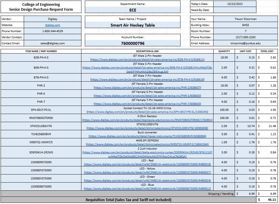
Figure 1: The final DigiKey order (Note that, despite using the “Senior Design Purchase Request Form”, this order was purchased by me).
Table Construction
- I assisted Alan in creating the MDF layer of the air hockey table where the sensor PCBs will be mounted at Bechtel Innovation Design Center (BIDC).
- First, Alan and I, under the supervision of a teaching assistant, cut the MDF to size using a panel saw.
- Second, the MDF was placed on a CNC router which had Alan’s CAD model loaded. The CNC router would perform two operations. The first operation consisted of using a 1/2” bit to cut a grid of 8x16 slots with the same depth as a sensor PCB and slightly wider and longer than a sensor PCB. The second operation consisted of using a 1/8” bit to cut channels within each of these slots to account for the THT pin headers. Alan and I loaded the 1/2” diameter and 1/8” diameter bits into the machine. After starting the CNC router, Alan had to leave with Ben to go to a different team meeting. I stayed to operate and supervise the machine, pausing between the operations to vacuum the sawdust since the CNC router’s vacuum was broken.
- Alan and Ben returned just as the CNC router finished the second operation. Alan and I deburred the slots using a brush, cleaned the area of sawdust, and performed the standard operating procedure for powering down and cleaning the CNC machine.
- Ben and I then carried the processed MDF board from BIDC to the lab.
Figure 2: A short video of the CNC router in the middle of performing the first operation.
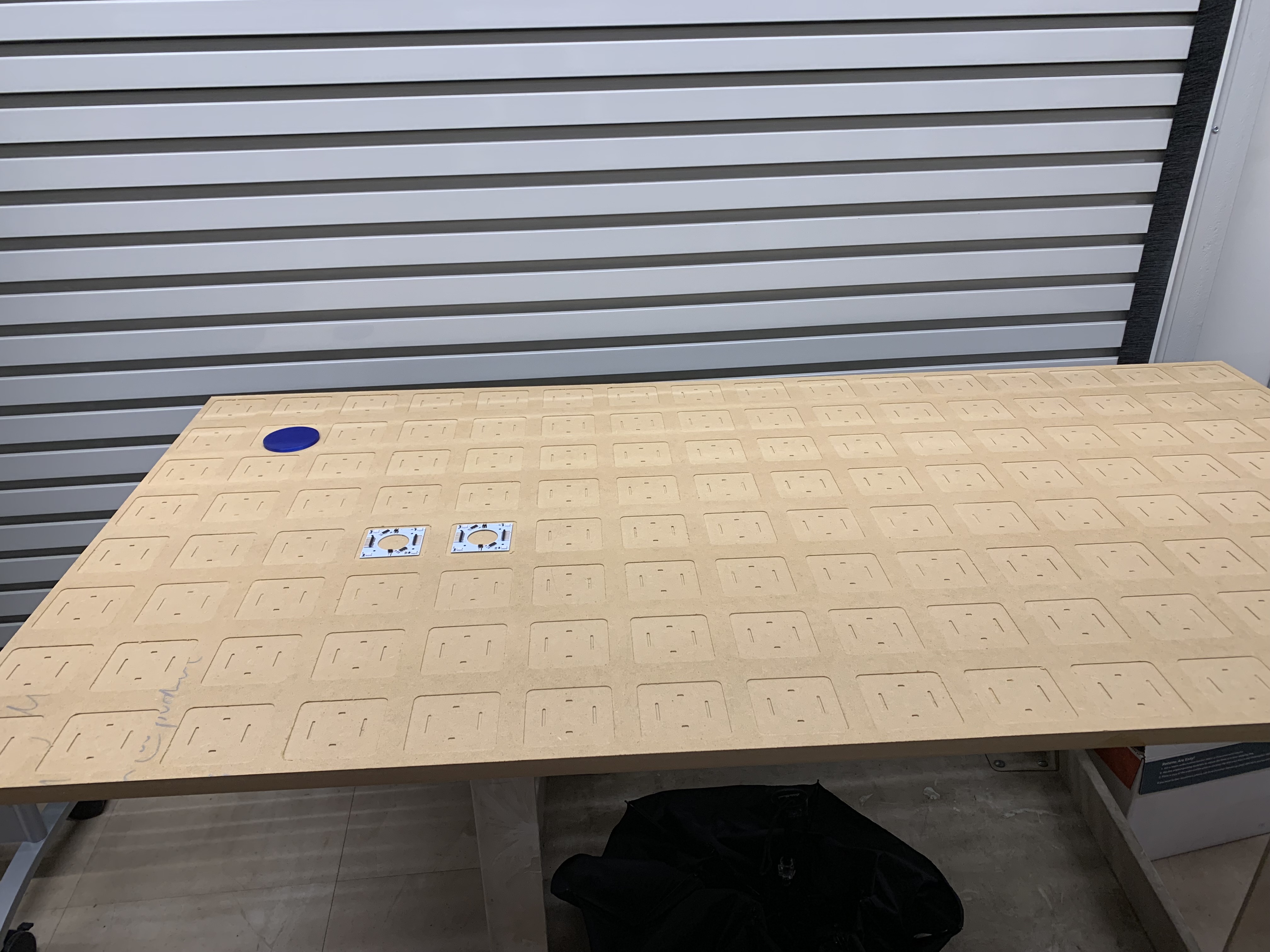 |
|---|
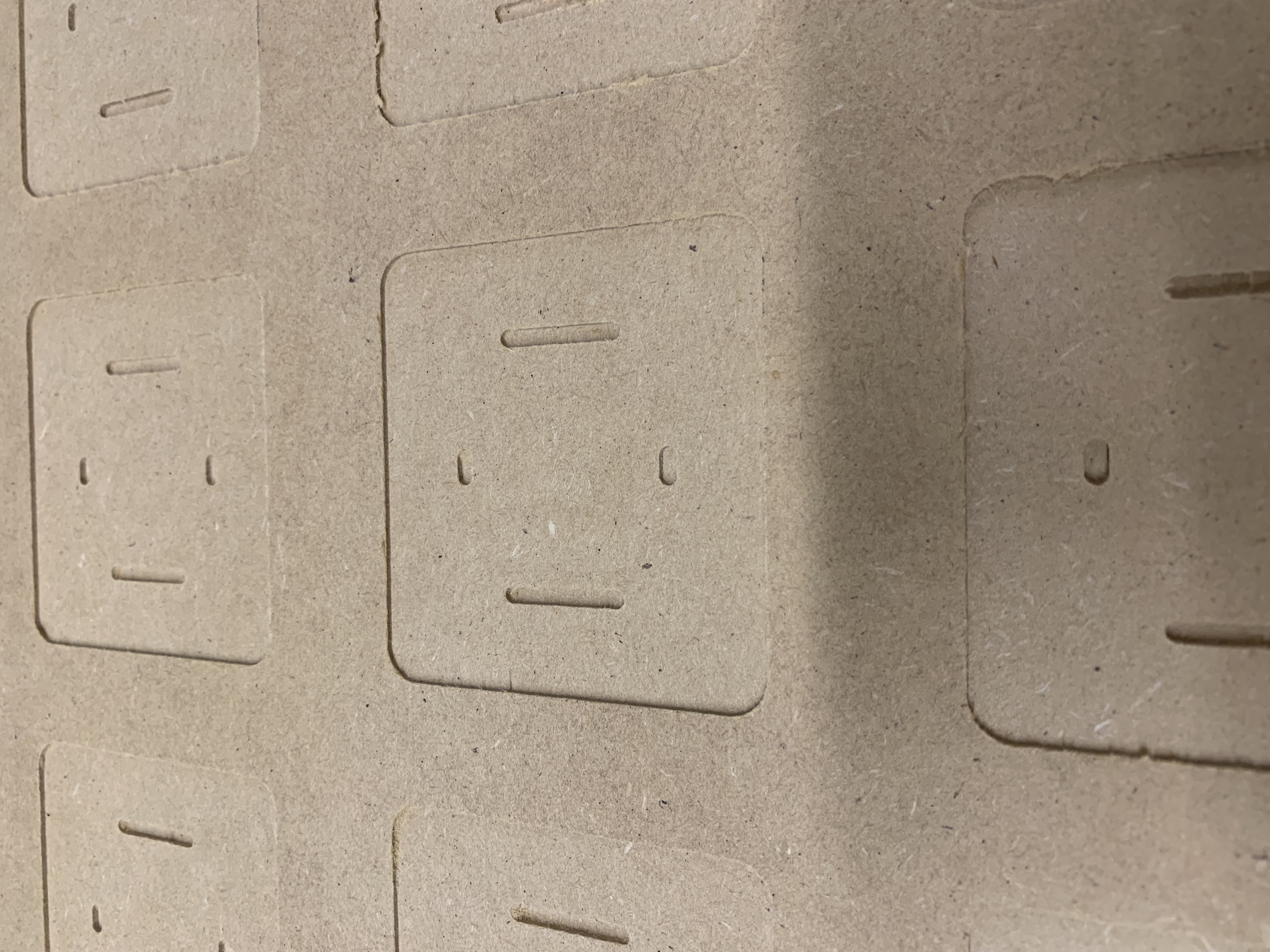 |
Figure 3: On the top, a full view of the processed MDF with two of the sensor PCB slots filled. On the bottom, a zoomed view of one of the sensor PCB slots.
EEPROM Driver
- Before this Thursday’s lecture, Ben and I began discussing how we should implement a driver for communicating with the external EEPROM, which will store persistent user data and animations, using SPI.
- After this Thursday’s lecture, the entire team discussed how loading and playing the animations should work. Which informed Ben and I on how we want to construct the driver.
- Ben and I currently plan to create a generic function for selecting and communicating with the external EEPROM using SPI, functions which implement the individual instructions available on the external EEPROM, and functions coordinating these instruction calls in a way that fits our intended use case. More details will follow in next week’s progress report as more planning and development is completed.
Next Steps:
Table Construction
- The MDF still needs to have holes cut through it to connect to the air hockey table’s blower before being considered finished. However, the MDF’s current state is enough to allow us to begin testing connecting the sensor PCBs in the final grid configuration once the assembled sensor PCBs are received.
- Alan is still the team member in charge of the air hockey table’s construction, but I will assist him when possible.
External EEPROM Driver
- As mentioned previously, the EEPROM driver has only just entered a concrete ideation stage. Ben and I will continue to plan the EEPROM driver.
- Once Ben and I have completed enough planning, we will then utilize pair programmingto develop the EEPROM driver, similarly to how we developed the hall effect and relay drivers.
Week 8 & 9
Date: 10/20/2023
Project Hours Since Last Report: 19
Cumulative Semester Project Hours: 108
Description of Individual Project Work Efforts:
Midterm Design Review
Slideshow:
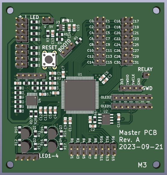
- Created the slides covering the electrical schematic, PCB layout, and PCB verification of the sensor PCBs. Each slide is accompanied by a list of talking points to hit during the presentation.
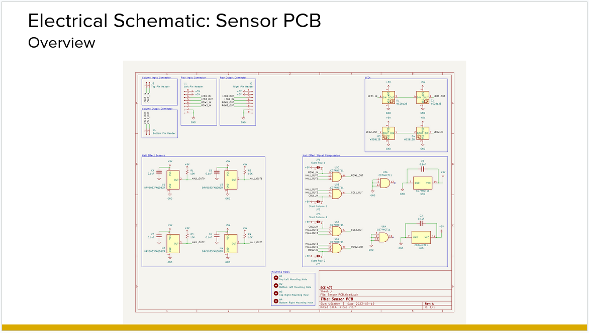
Figure 1: A sample of a slide created by me for the midterm design review presentation.
- A team meeting was held virtually over Fall break to finalize the slideshow, where I added suggestions to improve other sections of the presentation and received feedback on my section.
Website:
- Added notes to all team docs on the website with what needed to be updated.
Firmware
Migration from Nucleo-stm32f4 to Nucleo-stm32u5:
- Reviewed changes made by Will
State Machine:
-
Re-implemented the framework for the state machine on the new Nucleo-stm32u5’s firmware.
-
Following Alan’s review, implemented several recommended changes.
-
Following discussion with each of the team members individually, discovered that each team member has a different idea on how the state machine should be implemented and the responsibilities assigned to it. I paused work until a full team meeting to get everyone’s perspective and to straighten out how the state machine will integrate into the rest of the firmware. From this discussion, the team decided to have state changes be handled entirely by the state machine and each state will be implemented within the state machine itself, rather than abstracting this into a handler function. Therefore, polling will be used to get sensor data rather than utilizing external interrupts.
Goal Driver:
-
Created based on the LDR circuits’ outputs raising external interrupts.
-
After the aforementioned discussion with the team, reworked to use a polling-based system for software filtering.
-
Currently finished and awaiting review from the other team members.
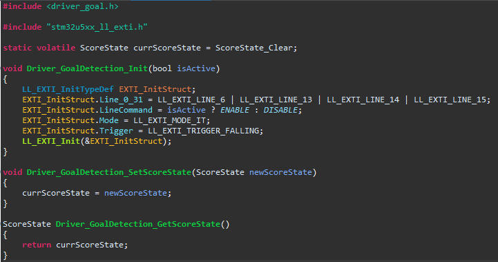 | 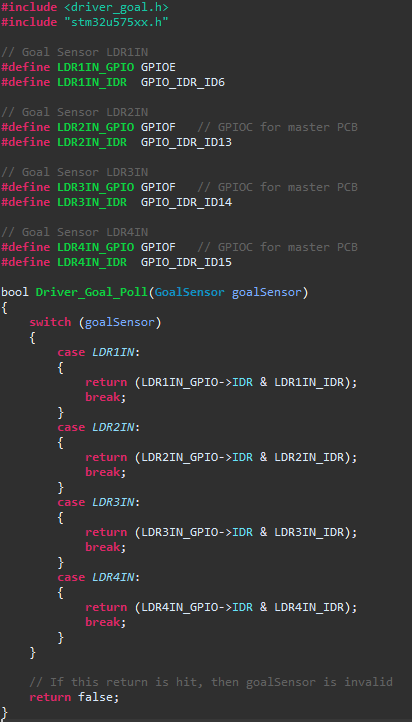 |
|---|
Figure 2: On the left, the old external interrupt-based goal driver. On the right, the new polling-based goal driver.
Hall Driver:
- Implemented the hall driver alongside Ben with pair programming. The driver polls the output of all the row and column outputs of hall effect sensors.
Relay Driver:
- Implemented the relay driver alongside Ben with pair programming. The driver turns on and off the power supply to the air hockey table’s fan.
Master PCB Rev A:
- After programming the hall driver and relay driver, Ben and I programmed the assembled rev A of the master PCB to test the drivers and the master PCB.
PCB Ordering - Sensor PCB
-
Ben discovered that a significant amount of money could be saved by having JLCPCB assemble the 128 sensor PCBs given the cost saved per component. When setting up the assembly order, JLCPCB did not have a sufficient stock of CD74HC11 for our order. I researched the differences between the CD74HC11 (datasheet) and the SN74HC11 (datasheet), which JLCPCB had enough of for our order. The SN74HC11 is available in the same package the sensor PCB uses (SOIC-14) and all differences listed in the datasheet were minor. Given the few requirements of the triple 3-Input AND gates for the sensor PCBs, no concerns were found with the SN74HC11. Furthermore, the SN74HC11 is meant to be Texas Instruments’ version of the CD74HC11 which was initially developed by Harris Semiconductor, which was acquired by Texas Instruments.
-
Edge rails were required for the sensor PCB to be assembled by JLCPCB. The team was concerned with how these edge rails would affect the sensor PCBs’ shape and size, given that the shape of the sensor PCBs affects our overall table design. I discussed how these edge rails are typically handled with Joe. He informed me that the edge rails are typically scored, either with a v-score or mouse bites, although he was unsure how JLCPCB handles edge rails. I relayed this conversation with Ben, who oversaw ordering the PCBs. Afterwards, Ben and I got into contact with a representative of JLCPCB who informed us that the edge rails are v-scored with the optional fee being to have JLCPCB break the boards before shipping. The team opted to forgo this optional fee and will break off the edge rails from the PCBs ourselves.
Figure 3: An example of the scoring performed by JLCPCB on the edge rails, courtesy of the JLCPCB representative.
Next Steps:
Goal Driver
-
After the team reviews my work, I will fix any issues that are found.
-
Otherwise, the driver is complete.
State Machine
-
I will lead any changes to the core framework of the state machine if any are needed as we continue developing the project’s firmware.
-
Otherwise, I will continue to work alongside the rest of the team to implement the required functionality of each state.
Week 7
Date: 10/06/2023
Project Hours Since Last Report: 12
Cumulative Semester Project Hours: 89
Description of Individual Project Work Efforts:
Hardware
-
After receiving the team’s Digikey order, I confirmed all components were included in the package. After which, I sent pictures of the shipping confirmation information to Ben to be sent to procurement.
-
Visited the ECE shop several times to gather electrical components needed by the team for testing or soldering PCBs.
Components included, but were not limited to: resistors (100 Ohm, 1 kOhm, 10 kOhm), capacitors (10 nF, 1 uF, 4.7 uF, 10 uF), various potentiometers, LDRs, LEDs (red, yellow, and blue), LM339, dupont wires (male to female), and 2n7000 THT mosfets.
Some components, such as white LEDs and 0.1 uF capacitors, were requested by the team but were unavailable from the ECE shop. -
Tested the new LDR circuit designed by Ben which iterated on my previous design. Ben’s new design switches the potentiometer to the positive input of the comparator, which allows for a modifiable voltage divider that is then compared to the LDR’s negative input. This allows for greater control over the comparator’s threshold and removes a resistor.
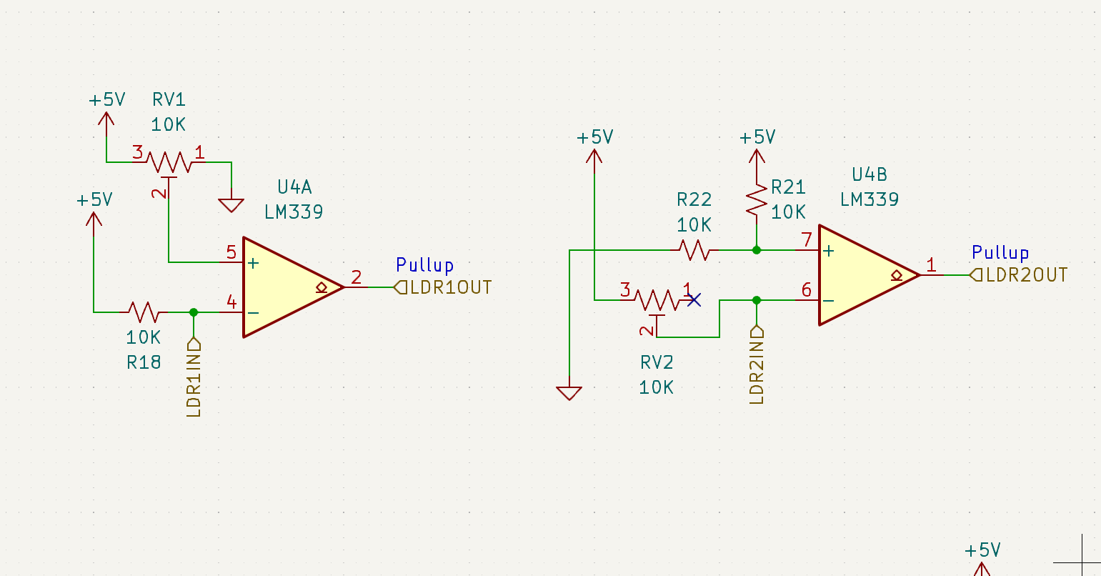
Figure 1: On the left, the Ben’s new LDR circuit. On the right, the old LDR circuit.
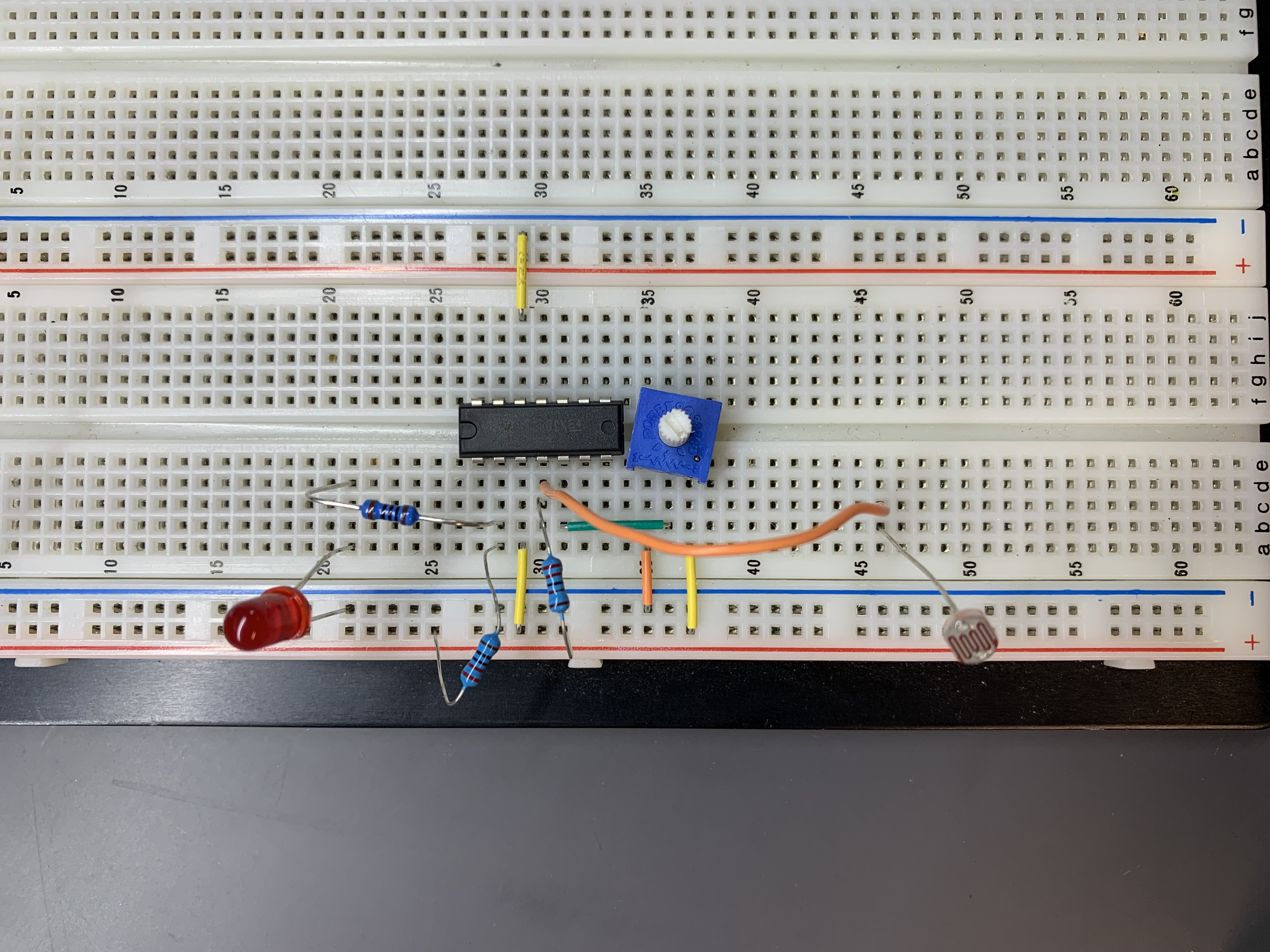
Figure 2: Test of the new LDR circuit.
- Assisted Ben and Alan in soldering Sensor PCBs. This primarily consisted of getting the required passives and breaking apart the 1x8 angled pin headers into 1x2 angled pin headers.
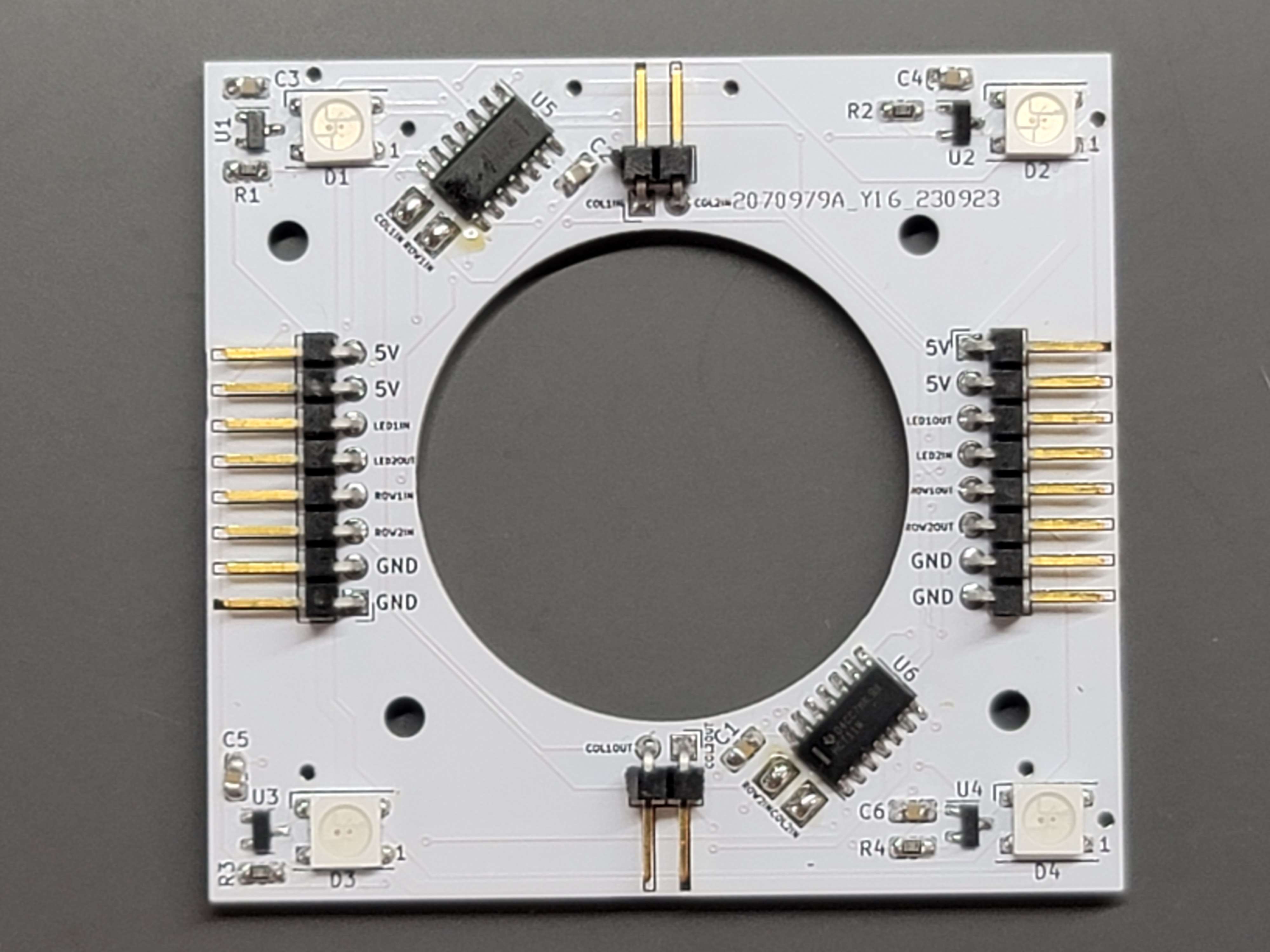
Figure 3: A soldered Sensor PCB.
-
Alongside the rest of the team, tested a single Sensor PCB (including an overnight stress test).
-
Alongside the rest of the team, tested a 2x2 and 2x3 group of connected Sensor PCBs.
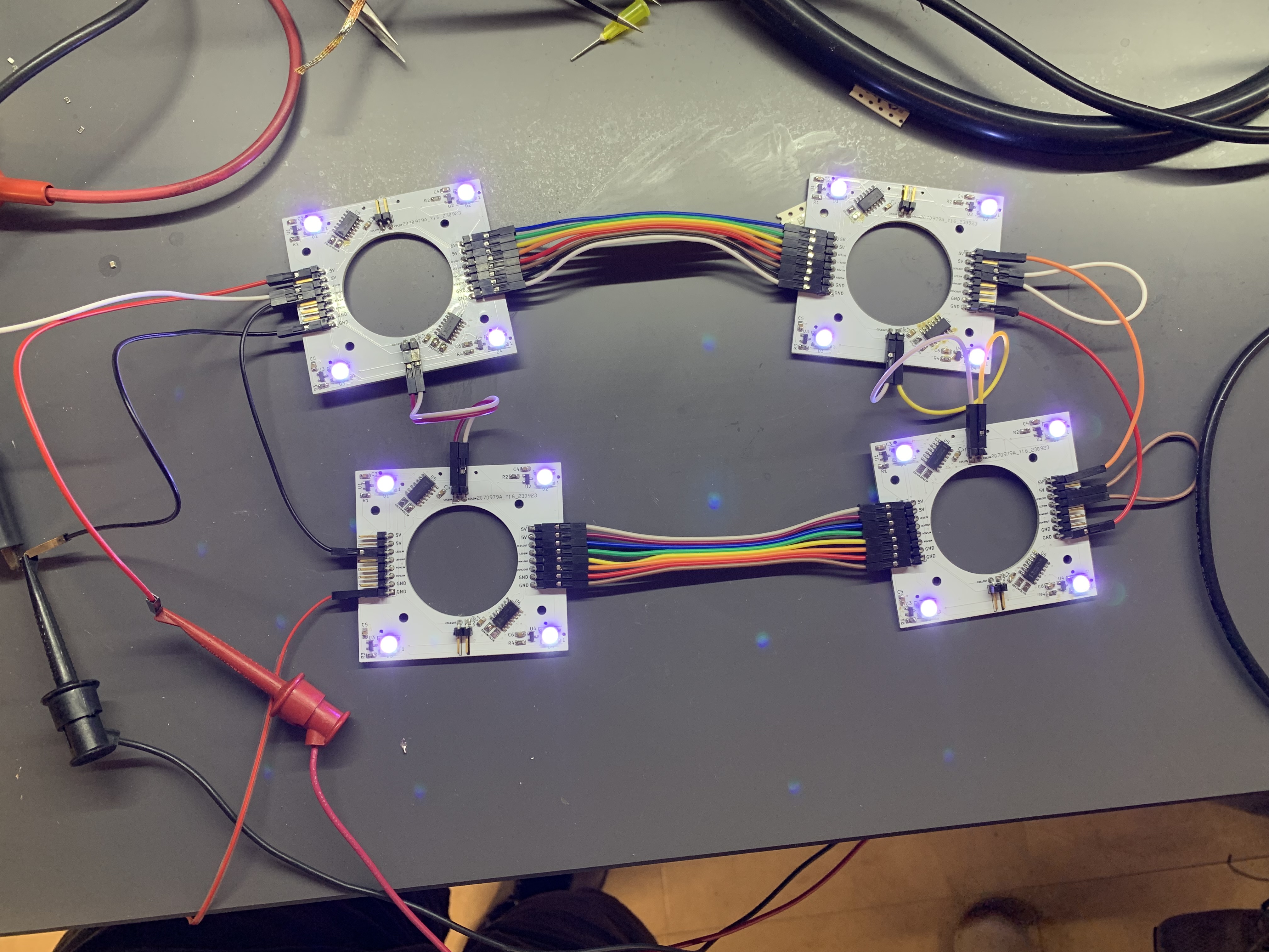
Figure 4: A 2x2 group of connected Sensor PCBs.
-
Assisted Ben in soldering and testing the buck converter on the Master PCB. We consulted the buck converter’s datasheet to make sure our design matches. After confirming that our design matched the datasheet’s suggested design exactly, we performed several tests using the lab’s digital multimeter. During our tests, we noticed that performing a test with the digital multimeter induced a transient response. We were unable to determine the issue before I had to leave, but Ben soon after discovered a faulty resistor connection. The digital multimeter’s impedance when probing the circuit is what induced the transient response. Fixing the faulty resistor connection fixed the buck converter.
-
Worked alongside Ben to test the encoder by building the PCB layout on a breadboard then measuring the rotary encoder’s response on an oscilloscope. The rotary encoder’s button worked as expected, but we were unsure whether the rotary encoder’s rotations were creating the expected output or not. Further testing was performed by Will.
Firmware
- Assisted Will in fixing the ASCII printable character alphabet for the OLEDs.
Sensor Schematic
- Minor improvements made based on feedback from Ben. (See figures 5 and 6 below for a comparison)
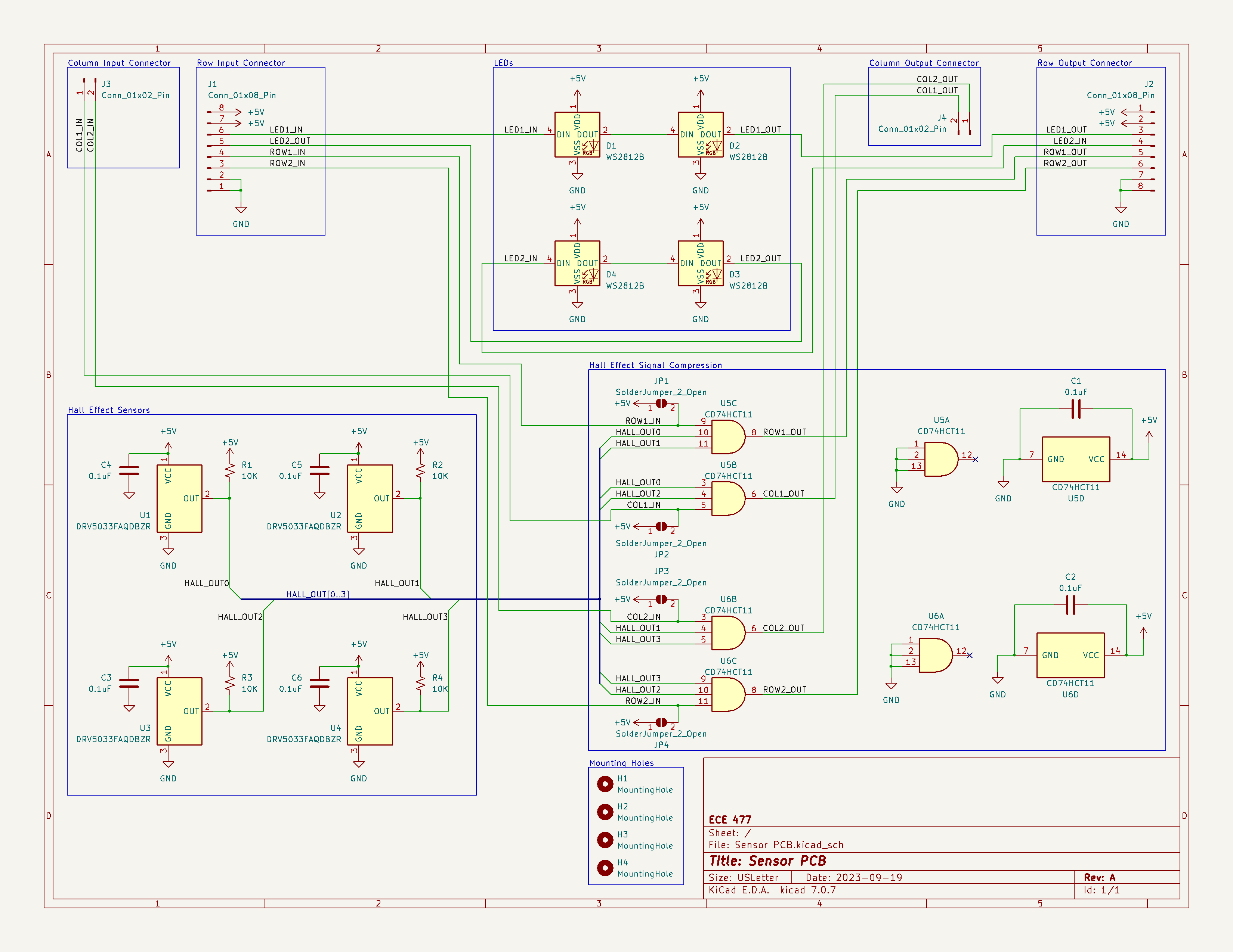
Figure 5: Sensor schematic before Ben’s feedback.
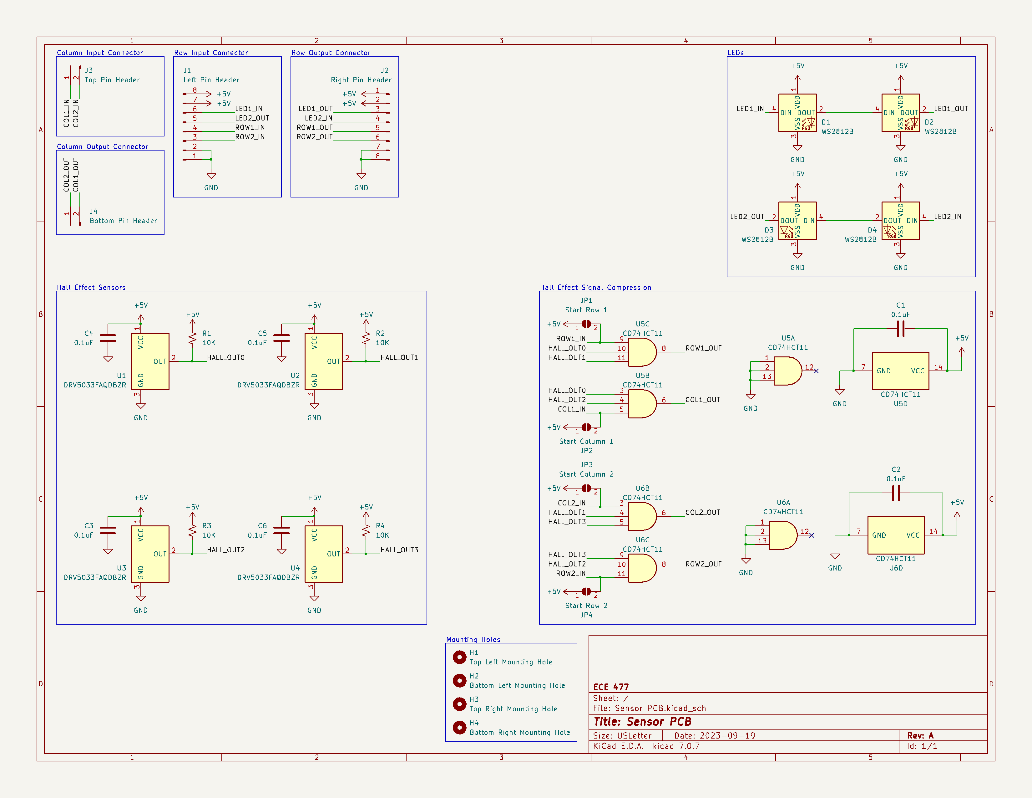
Figure 6: Sensor sechematic after Ben’s feedback.
Midterm Design Review
-
Coordinated with the team what needs to be done before the midterm design review; hardware, firmware, and presentation. Hardware and firmware are both ready for the presentation. For the slideshow, I am responsible for the electrical schematic and PCB layout for the Sensor PCB. After completing my section, I will give feedback on the other team members’ sections.
-
Added notes to design documents marking what needs to be updated to reflect our current design.
-
Took pictures to illustrate the blower set-up.
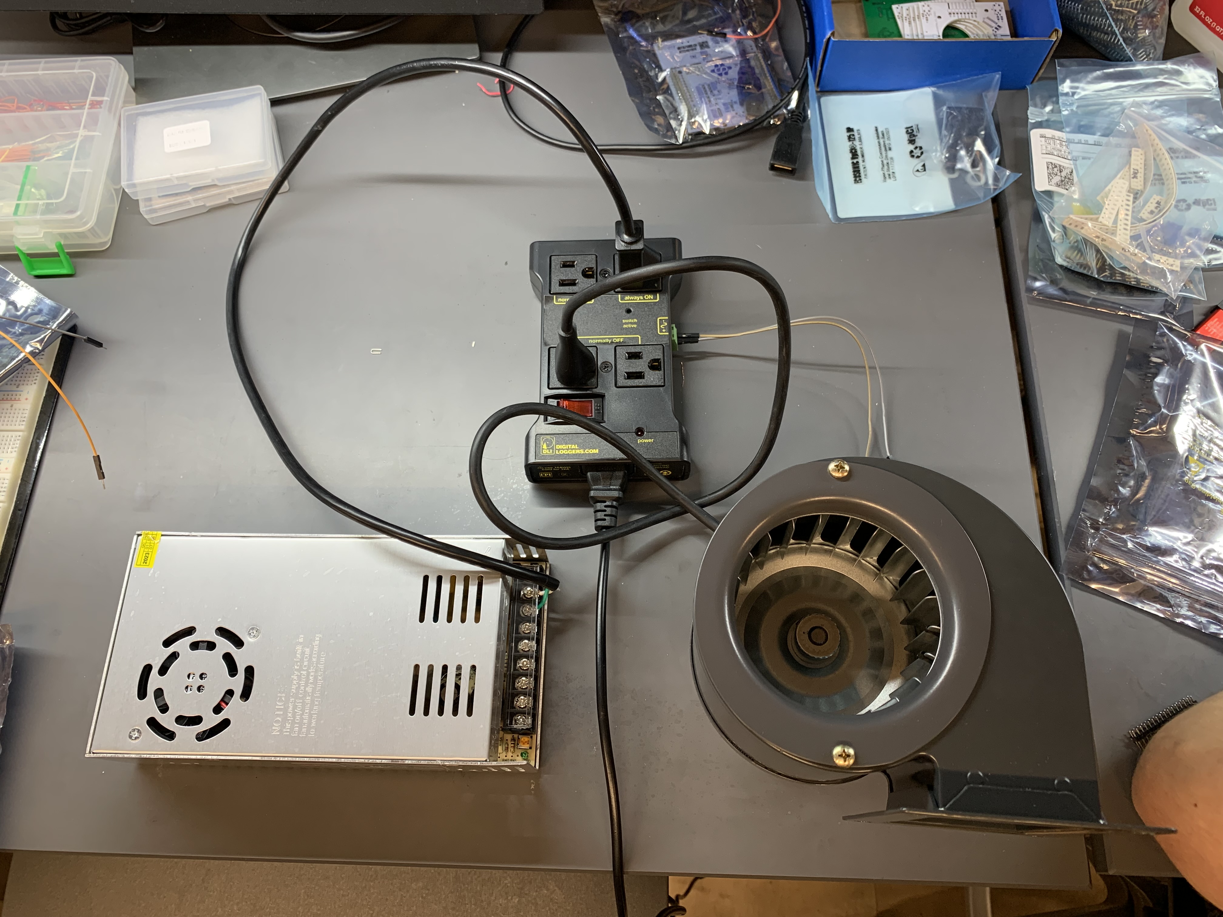
Figure 7: Blower setup.
Next Steps:
Midterm Design Review
-
As mentioned previously, I will create the slides for the electrical schematic and PCB layout of the Sensor PCB.
-
After completing my slides, I will provide feedback for the other members.
-
I will work alongside the rest of the team to edit the team’s design documents using the notes that I have already added.
-
I will work alongside the rest of the team to update our team website in preparation for the midterm design review.
Firmware
-
I will work with Will to convert our firmware to the new microcontroller.
-
I will fix the goal detection firmware to prevent multiple interrupts being generated by the same goal. This will be done by disabling the goal detection interrupts while the first interrupt is being serviced, then re-enabling the interrupts afterwards.
Sensor PCB
- Currently, the team has not discovered any issues with the Sensor PCB that require a revision. However, if an issue is discovered, then I will lead development of revision B of the Sensor PCB.
Week 6
Date: 09/29/2023
Project Hours Since Last Report: 15.5
Cumulative Semester Project Hours: 77
Description of Individual Project Work Efforts:
A6 - Mechanical Overview
-
Added appendices to the document.
-
Wrote section 2.0 “Project Packaging Description.
A7 - Bill of Materials
- Worked alongside the team to complete the document, primarily adding supplier part numbers and fixing formatting.
A8 - Software Formalization
- At Will’s request, I read his drafted document and added a few comments for recommended changes.
Sensor Schematic
- Updated the sensor board’s schematic to improve readability, while being electrically equivalent.

Figure 1: Previous Sensor Schematic
Figure 2: New Sensor Schematic
Hardware Testing
-
During this week’s ManLab, alongside the rest of team, performed ad-hoc testing of two DRV5033 to ensure that they work as we expected.
-
Alongside Alan and Ben, tested the blower.
Software Development
Super-loop & State Machine:
- Created an enumeration with all states of state machine.
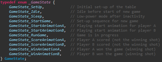
Figure 3: State Machine Enumeration Code
- Created the framework for the super-loop that is invoked every SysTick (1 ms) and coordinates function calls based on the current state.
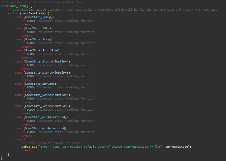
Figure 4: Super-Loop Framework Code
Goal Detection:
-
Created rising edge external interrupts attached to the pins that receive the goal detection circuit’s output signal.
-
Created a handling function to be called by the external interrupts which handles the state transition and increments the appropriate player’s score assuming the correct conditions are met.
-
Added variables to store the data required by these functions, such as each players’ score and the number of points to win. As well as “getter” and “setter” functions to access these variables.
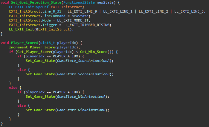
Figure 5: Goal Detection Enabling/Disabling & Handling Functions
Next Steps:
Software Development
-
While the firmware builds with my changes, I will need to test the work done on the super-loop, state machine, and goal detection using the NUCLEO-F411RE.
-
Once the NUCLEO-U575ZI-Q is received from the team’s DigiKey order, then the firmware will need to updated from NUCLEO-F411RE to NUCLEO-U575ZI-Q. After which, I will need to retest and ensure that all functionality has been retained.
Schematic & PCB Layout
-
Once the electrical components has been received from the team’s DigiKey, then the team will need to begin assembling a master PCB and the sensor PCBs. After which, the team can begin testing.
-
After the PCBs have been tested, then the team will begin working on revision B of the schematics and PCB layouts based on our findings. Ben will lead development on revision B of the master schematic, and I will be available to help him. I will lead development on revision B of the sensor schematic.
Week 5
Date: 09/22/2023
Project Hours Since Last Report: 18.5
Cumulative Semester Project Hours: 61.5
Description of Individual Project Work Efforts:
Microcontroller Pin Assignment
- Alongside Ben, I utilized the STM32CubeIDE’s visual pin assignment tool to determine the pin assignments for our project.
PCB Design
- Once we decided on pin assignments, we wired the microcontroller accordingly in the Master PCB schematic Ben had previously created.
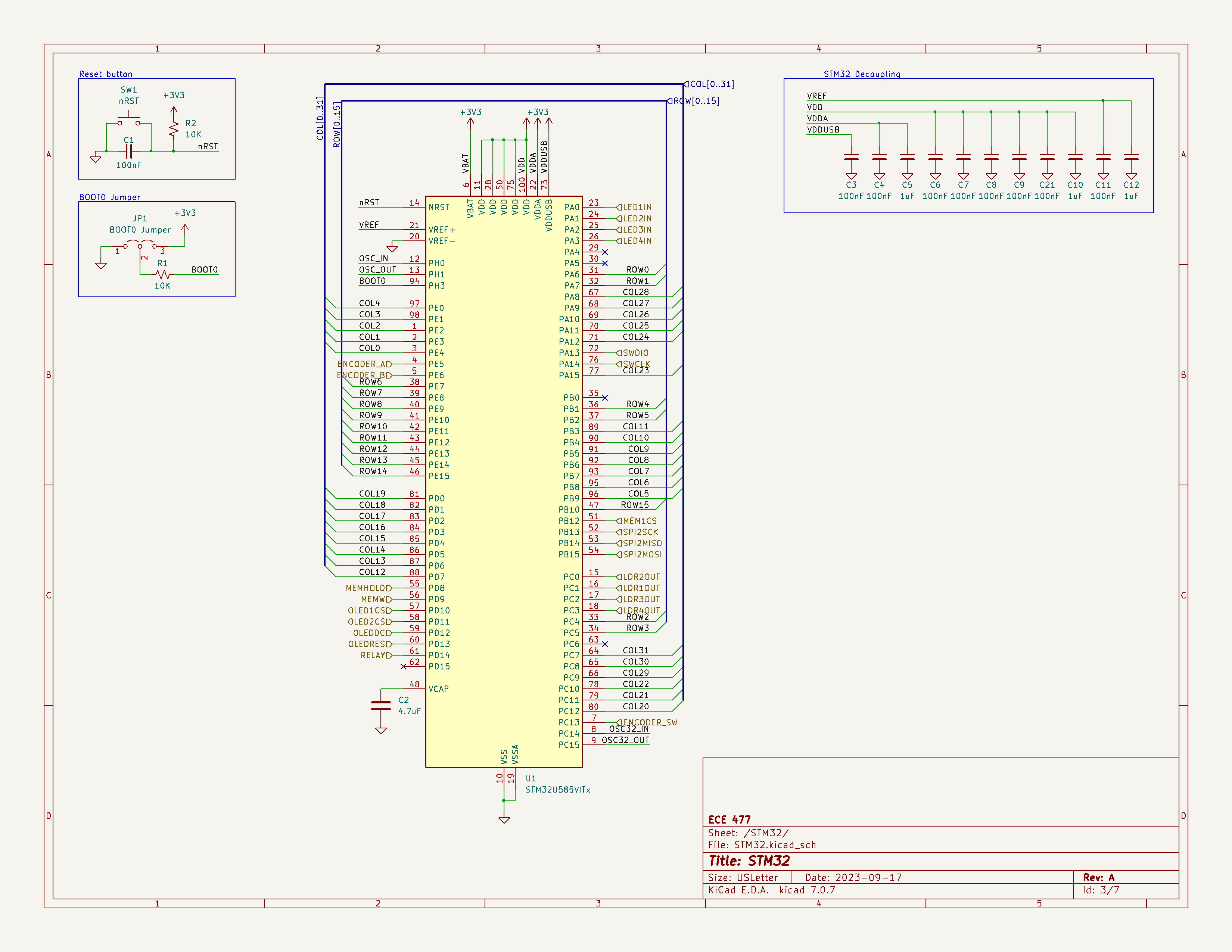
Figure 1: Current Master PCB Schematic
-
I learned about assigning component footprints, laying out components, and routing in KiCad from Ben.
-
I assisted Ben in routing a portion of the Master PCB.
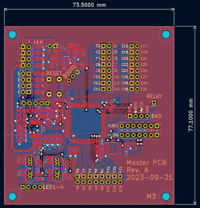 |  |
|---|
Figure 2: Current Master PCB
- I lead designing the Sensor PCB schematic.
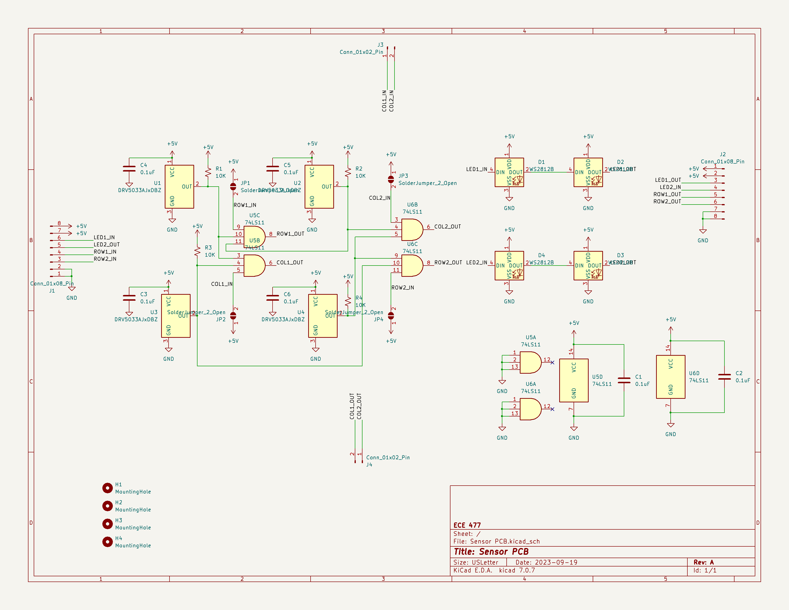
Figure 3: Current Sensor PCB Schematic
- I lead assigning component footprints, laying out components, and routing in KiCad.
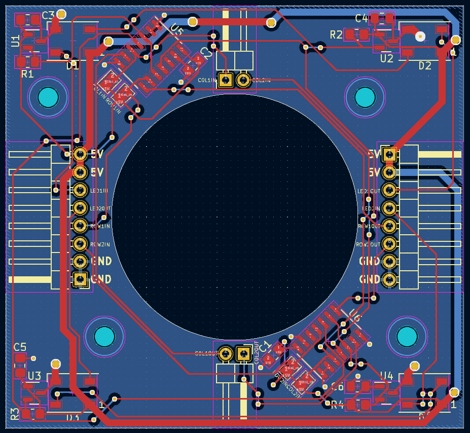 | 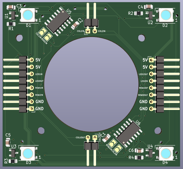 |
|---|
Figure 4: Current Sensor PCB
- I revised the Master PCB and Sensor PCB alongside Ben using Dr. Walter’s initial comments.
Puck Tracking
- Ben pointed out to the team that the sampling rate of the TMAG5231, the digital hall effect sensor we planned to use, was too low for our requirements. This prompted Ben, Will, and I to research and discuss alternatives.
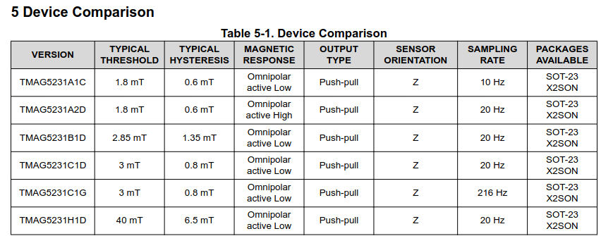
Figure 5: TMAG5231 Sampling Rate Table
- We eventually decided to switch to the DRV5033. Luckily the DRV5033 has the same pinout and footprint as the TMAG5231, which reduced the amount of work required by the team to amend the PCB designs. Unfortunately, switching hall effect sensors increased the bill of materials by approximately $120. However, the team feels confident that none of the viable alternatives would be cheaper.
Mechanical Discussions
- I participated in team discussions about the mechanical design of the table during the mandatory lab.
A6 - Mechanical Overview
-
I researched commercial products’ packaging to analyze for the document.
-
I wrote the first two sections analyzing two commercial products’ packaging.
Next Steps:
PCB Design
- If Dr. Walter or Joe provide critiques of our PCB designs, then revising and correcting the Master PCB and Sensor PCB will be the team’s top priority.
Puck Tracking
-
If we can get some DRV5033’s, then the team will need to perform tests to ensure that the sampling rate will not be an issue and that the component still works as we expect.
-
Otherwise, if the team is unable to get access to some DRV5033’s from the lab, then we will need to order some to test alongside the PCBs.
Firmware
-
Week 4’s progress report stated that I would work on developing firmware for goal detection and the game state machine. However, the team has since switched to a new microcontroller that the team does not have access to yet. We plan to order a Nucleo board for testing. In the meantime, the team decided that finishing the design for the PCBs was of utmost importance. Therefore, I have shifted to that.
-
If we are unable to do any hardware testing and the PCBs do not need more work, then I will return to working on the firmware.
A6 - Mechanical Overview
-
I need to write section 2.0, project packaging description.
-
I need to add the appendices to the document. Although most of the work towards these appendices has already been completed.
-
Finally, I will need to revise the document to create my final draft for submission. At this point, I will ask my team for comments on the document.
A7 - Bill of Materials
- I will assist the team in creating the bill of materials.
Week 4
Date: 09/15/2023
Project Hours Since Last Report: 12
Cumulative Semester Project Hours: 43
Description of Individual Project Work Efforts:
Team Meetings
- Coordinated when the team would work on the component analysis.
Hardware
-
The magnets ordered last week arrived, which Ben and I promptly began to test. However, during the ad-hoc testing before the formal testing began, I suggested that we should consider switching to a digital hall effect sensor. The team’s original intent with the analog hall effect sensor was that the threshold could be dynamically adjusted by the microcontrollers performing the ADC conversions. However, now that the team planned to condense the signals using digital logic, the analog hall effect sensors’ signals would need to be converted to a digital signal using an op amp or comparator. Thus, my suggestion to use a digital hall effect sensor would remove this intermediate step. A digital hall effect sensor within the lab was used as a proof of concept, and a sample of digital hall effect sensors have been ordered. Unfortunately, this delays testing an additional week.
-
Preceding the work done on the component analysis, the team met virtually Wednesday afternoon to finalize component selection. As part of this, the team performed a required I/O count, which was then used to ensure that the microcontroller selected by the team had enough GPIO pins of the correct type.
Firmware
-
Before working to add features to the project’s firmware, I reviewed and familiarized myself with the work that had been done so far. Most of the previous work has been the LED driver developed by Ben and Will.
-
The Smart Air Hockey Table’s firmware uses a super-loop architecture where the super-loop is invoked according to a timer. I have begun implementing the timer-based super-loop but will need to continue development next week.
-
The game state machine determines what actions are performed during each iteration of the super-loop. A basic implementation was started; however, development was paused until the team had time during the mandatory lab to discuss the form of the state machine. The finalized flowchart can be found on Alan’s week four progress report.
A5 - Component Analysis
- While the entire team worked on the document together, I led the initial draft of the “1.1 Analysis of Microcontroller” and “1.5 Analysis of Goal Detection Sensors”. After I received feedback from the team on my draft, I then revised both sections. I also provided feedback on the rest of the document for my team members to review.
Next Steps:
Puck Tracking
- As mentioned in the hardware section above, Ben and I will test the new, digital hall effect sensors once they have been received. We will gather measurements from “slide-by” experiments performed at various heights above the hall effect sensor. (https://www.ti.com/lit/ds/symlink/tmag5231.pdf)
Goal Detection
- As mentioned in the week three progress report, I will raise an external interrupt when the photoresistor-based circuit detects that a goal has been scored. Unfortunately, I was unable to begin work on this feature as I contracted an illness this week. The team was made aware of this setback, and we decided that this feature could be delayed until I recover.
Game State Machine
- I will implement the game state machine as shown in Alan’s week 4 progress report. Some state transitions are not able to be implemented yet, so the firmware will include placeholders for where the transitions will later be implemented.
Week 3
Date: 09/08/2023
Project Hours Since Last Report: 14
Cumulative Semester Project Hours: 31
Description of Project Design Efforts
Puck Tracking
The development of puck tracking has continued in two ways.
- Firstly, the team has discussed which magnet would be best to use in the puck. While all team members have contributed to this conversation, Ben and I have discussed the topic the most and jointly took charge in making the final decision. Ben and I’s discussions centered around whether the puck’s magnet should try to maximize “pull force” or “surface magnetic field.” After some research and informal testing, we determined that “pull force” was a better rough indicator, but we would also need to note the shape of the magnet’s magnetic field. The shape of the magnet’s magnetic field is almost entirely dependent on the shape of the magnet itself, as can be seen in the figure below. Ben and I looked at the field of several different shapes of magnets, and disk (with an “axial” magnetic direction) had the best shaped magnetic field for our application. However, we were unable to determine if we could create a configuration of multiple magnets which would be better. Hence, we ordered some smaller disk magnets and small cylinder magnets along with the large disk magnet we currently plan to use.
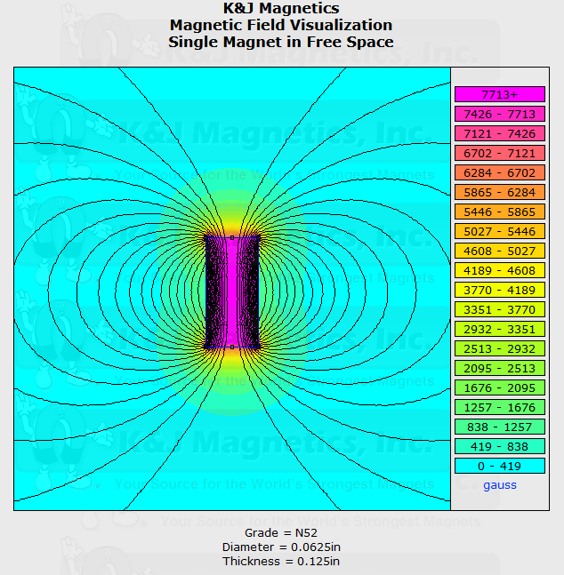 | 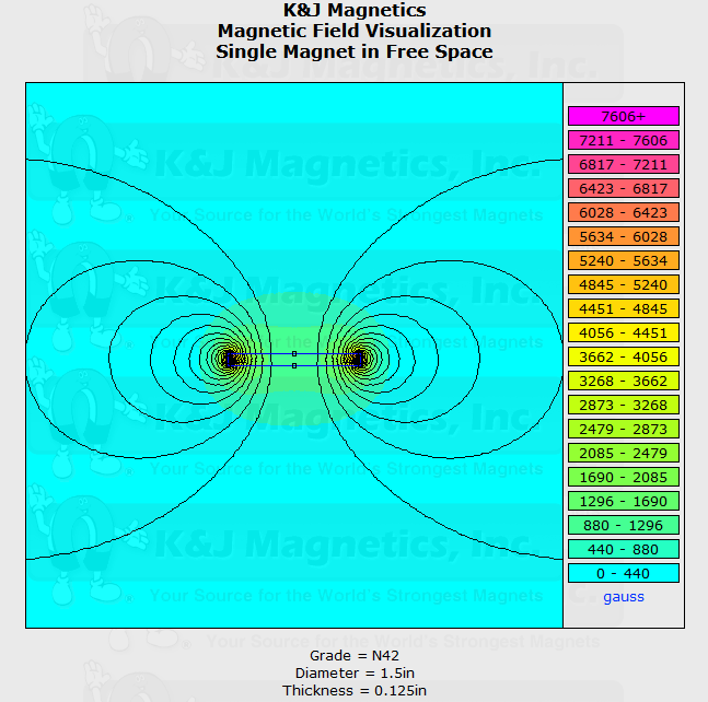 |
|---|
Figure 1: Example magnetic fields of a cylinder magnet (left) and disk magnet (right) provided by K&J Magnetics, Inc.
- Secondly, the team has had several discussions about ways to reduce the time it takes to read the hall effect sensors. A discussion between Ben and I have dramatically changed our planned approach to reading the hall effect sensors. Previously, we had planned to use “row master” microcontrollers which would be responsible for reading, processing, and reporting the hall effect sensor data to the main microcontroller. However, if we convert the hall effect sensor to a digital signal, then we can use logic gates to compress the hall effect sensors into a digital signal on if the puck is in that row or column. This method is similar to a suggestion made during our Initial Project Proposal, where it was suggested to create a lattice of IR sensors across the play field. The IR sensor method wouldn’t work as anything on the play field could trip the sensors, but only the puck’s magnet will trigger the hall effect sensors.
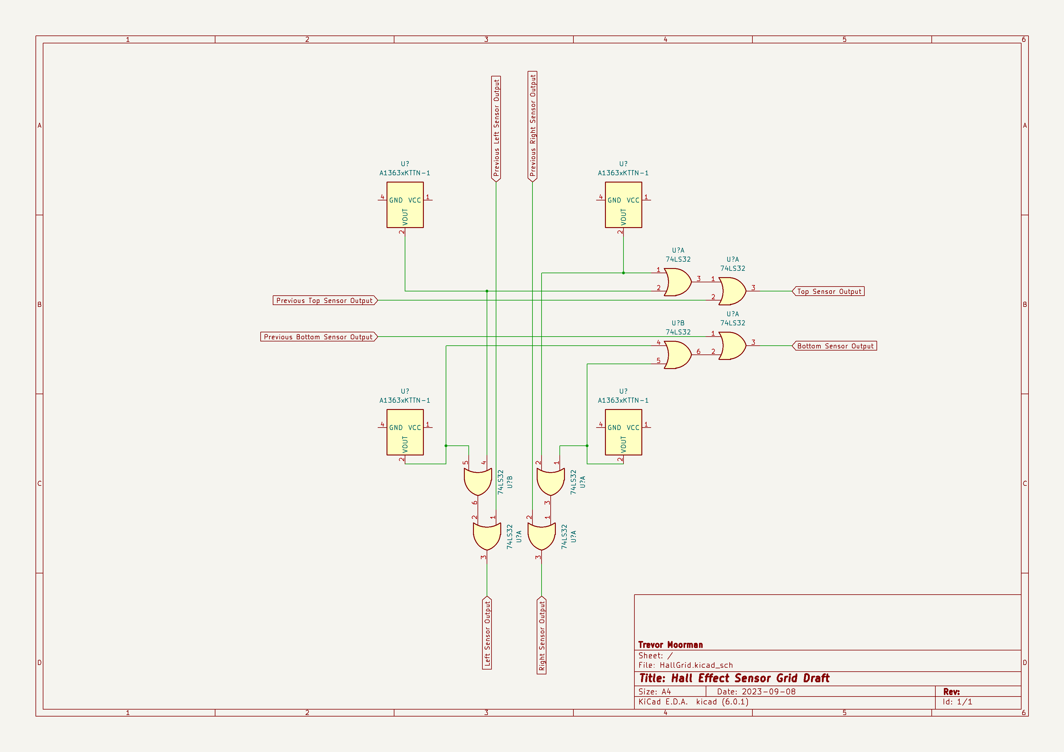
Figure 2: Partial diagram showing the proposed OR gate solution
Goal Detection
- A quick, proof-of-concept circuit was constructed during this week’s mandatory lab to showcase how a photoresistor could be used for goal detection. However, this circuit used an op-amp when a comparator would work better. Thus, the next day I went to the ECE shop, grabbed some comparators, and built a similar circuit, a picture and diagram of which can be seen below.
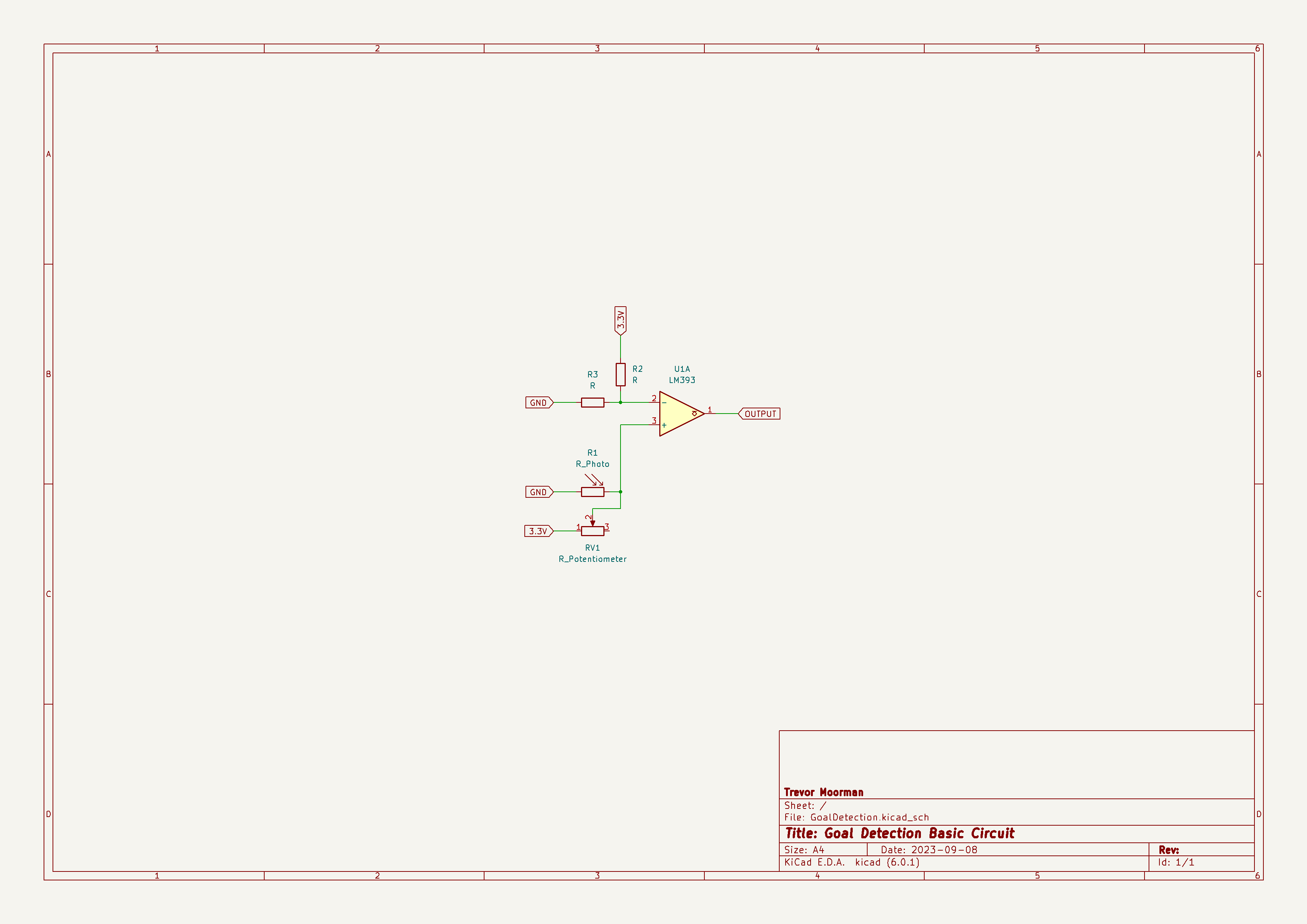 | 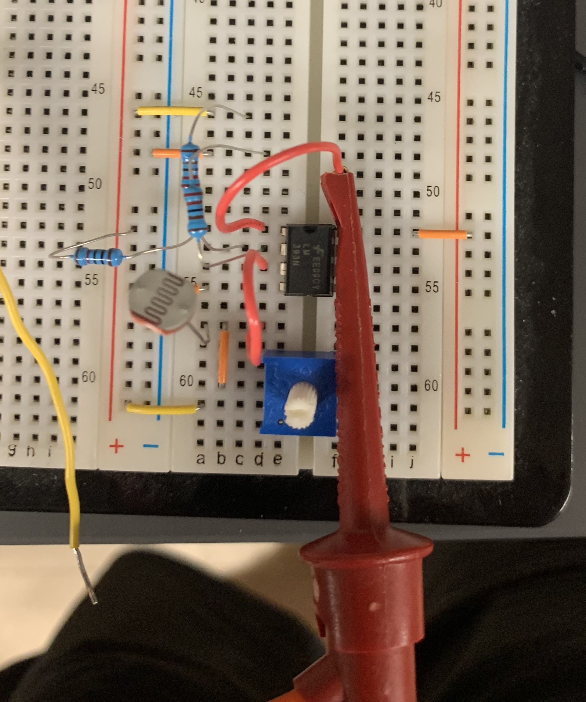 |
|---|
Figure 3: Schematic of photoresistor circuit (left) and picture of built photoresistor circuit (right)
Project Description and PSDRs
- I have drafted a new project description and adjusted the PSDRs based on feedback from instructional team given during the last mandatory lab session. I am waiting to receive feedback from the other team members on my changes before updating the team’s website.
Next Steps
Puck Tracking
-
Once the new magnets arrive, Ben and I plan on testing how the hall effect sensor’s output changes as the puck moves laterally above the sensor at different heights. This will give the team an idea of how far the playing field can be above the sensors.
-
While preliminary testing showed that putting insulating materials between the magnet and the Hall effect sensor has no discernible effect, we will verify this with the new magnets as well.
-
After this testing, further work on puck tracking will likely require using a model of a portion of the table’s playing field.
Goal Detection
-
I will connect the output of the circuit to one of the microcontroller’s GPIO pins, then develop firmware for detecting when a goal is scored. This will likely be done with an external interrupt, although I will need to discuss with the team how exactly this subsystem should interact with the overall system.
-
Later, this will need to be integrated with the overall system. Namely the game state.
Project Description and PSDRs
- As mentioned previously, I am currently waiting for feedback from all the other team members. Once I receive this feedback, I will amend the description and PSDRs further then update the team’s website.
Week 1 & 2
Date: 09/01/2023
Project Hours Since Last Report: 17
Cumulative Semester Project Hours: 17
Description of Project Design Efforts
Initial Project Proposal
- Before meeting with the team, I emailed Dr. Walter for clarification on some of his comments that were concerned with the section that I had written. Using this clarification, I found alternate commercial products to use in our initial project proposal.
- During the meeting, I helped keep the team focused on the task at hand and gave suggestions on how we should prioritize our time. This was vital to our success given our limited time to meet.
Final Project Proposal
- During the meeting, I noticed that some of our conversations repeated past discussions. To help keep the team on the same page, I took notes for the meeting. Alan later helped format the notes that I took, and the team agreed to take meeting notes going forward.
A2 - Technical Specification
- I took notes during the draft meeting and reminded the other team members to add to the meeting notes as well.
- Towards the end of the meeting, Alan had to leave so I suggested that we divide the sections between team members.
Team Organization
- Scheduling the meeting turned out to be a challenging task given the team members’ busy and rigid schedules. It often took team members a long time to respond to questions about their schedule and this led us to rescheduling our meeting a few times. I worried that this could be a recurring issue throughout the semester, so I first suggested that the team should schedule one or two regular meeting times outside of the mandatory lab. Unfortunately, the other team members did not like this approach as none of them felt they would be able to consistently keep a block of time free. As an alternative solution, I suggested that we should use When2Meet to schedule our meetings. When2Meet made scheduling the final project proposal meeting much easier, and the team has agreed to use this tool in the future.
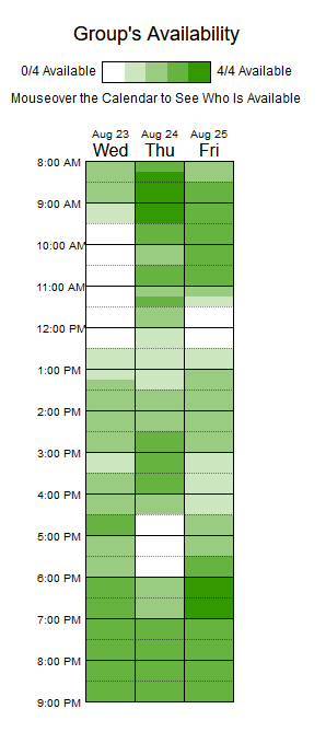
Figure 1: Example When2Meet from week 1
Team Website
- I suggested that we should add a folder to our project repository on GitHub that mirrors our uploaded website. This would protect us from potentially losing data, allow for version control, and prevent several members from attempting to make changes concurrently. The team decided to adopt my suggestion.
Hardware
- EE Shop: At the beginning of the week, I visited the EE shop on behalf of the team to look for hall sensors that the team could use for feasibility testing. I was able to get two Hall effect sensors which were the exact model the team had been looking at previously. I also looked for any other components that may be useful for prototyping, but did not find anything else.
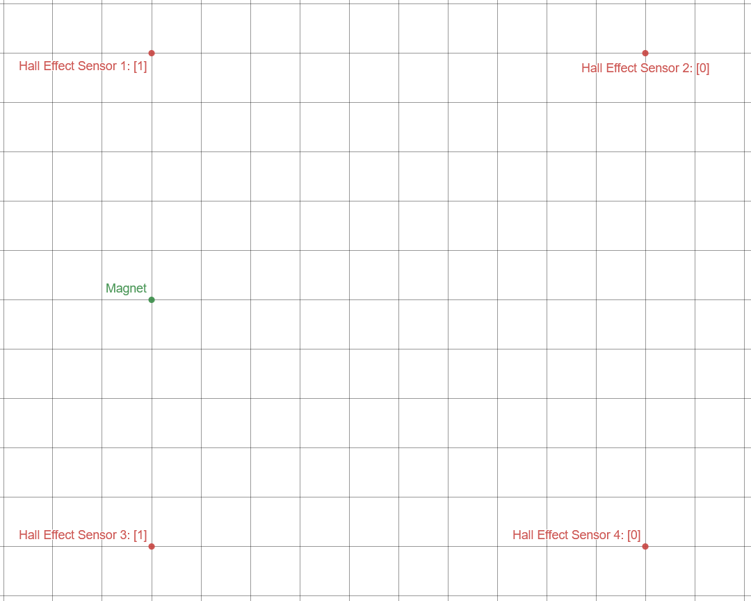
- Design Discussion: During the mandatory lab on 8/30/2023, Alan, Ben, and I discussed the design of the daughter PCBs. Our discussion primarily focused on how the Hall effect sensors and LEDs should be laid out and how data will flow between the microcontrollers. My main contribution to the discussion was suggesting one level of the microcontrollers should convert the hall effect sensor readings to a digital signal based on a threshold. The location of the magnet could then be determined by averaging the position of all Hall effect sensors that have been “triggered”, rather than more complex computations based on the Hall effect sensor’s magnitude readings. This would decrease the amount of data that would need to be transferred between the microcontrollers. Alan and Ben are both interested in exploring this method further, with Ben proposing that we include multiple thresholds to increase the resolution while still compressing the data. Feasibility testing with the Hall effect sensors will give us a better idea on whether this method of data compression will work.
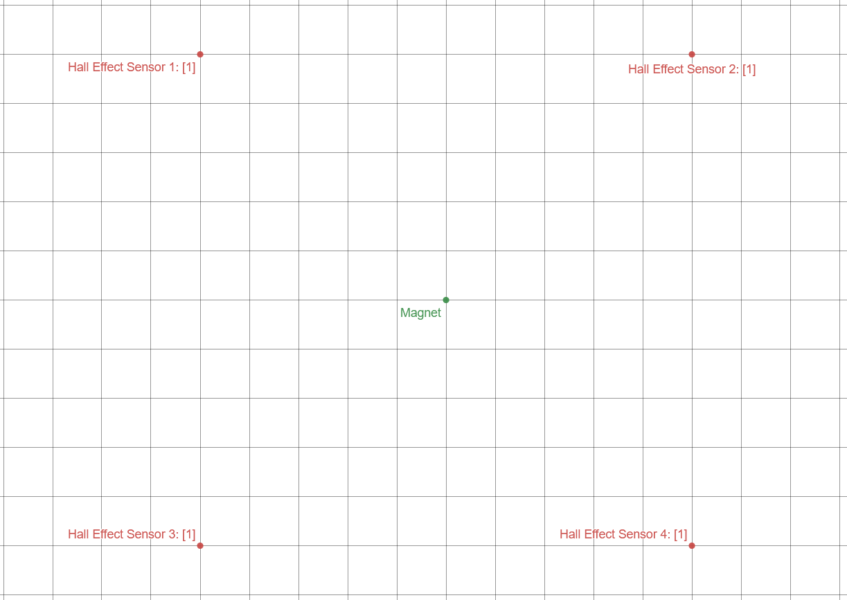 |  |
|---|---|
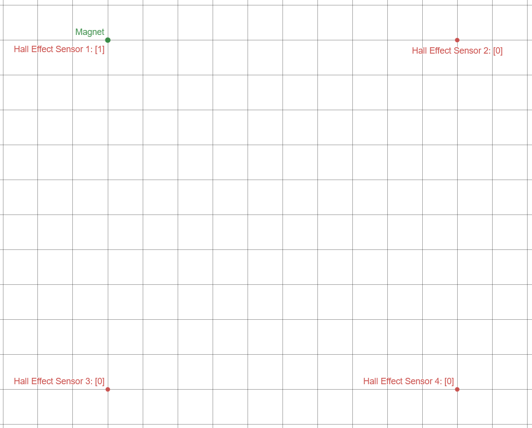 | 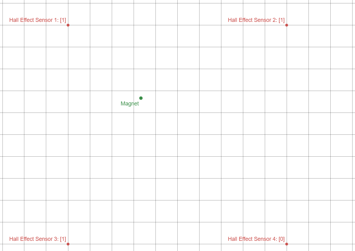 |
Figure 2: Puck detection examples using the threshold method
Software
- Given that we will be using STM32 microcontrollers, the team decided that we will use STM32CubeIDE for primary development. I have experience with this IDE from my internship last semester, so I gave Will a quick overview of the features STM32CubeIDE provides. I especially focused on highlighting the code generation and providing a high-level explanation of the LL drivers, HAL drivers, and middle-ware available.