Progress Report for Will
Week 14 & 15
Date: 12/1/2023
Project Hours Since Last Report: 50
Cumulative Semester Project Hours: 189
Description of Project Design Efforts
Everything Table Construction
In the first few days of week 14, the team spent considerable time working in the lab to attempt to finish constructing the table. Although there was too much done to succinctly cover in this report, I remember plenty of drilling, screwing, sawing, dremeling, filing, cutting wires, stripping wires, soldering wires, heatshrinking wires, cable managing, and incremental testing. We spent a couple of very late hours in the lab tracking down a tricky bug with our LED matrix, only for it to somehow be solved by giving up and moving on with assembling the matrix. There were some instances of questionable carpentry decisions being made, but it all turned out fine in the end. Although soldering pin headers to the sensor PCBs and screwing them into the table were time consuming in their own right, plugging in the wires and taping them down proved to be even worse. I am thankful that, due to our efforts, the end result looks fairly impressive.
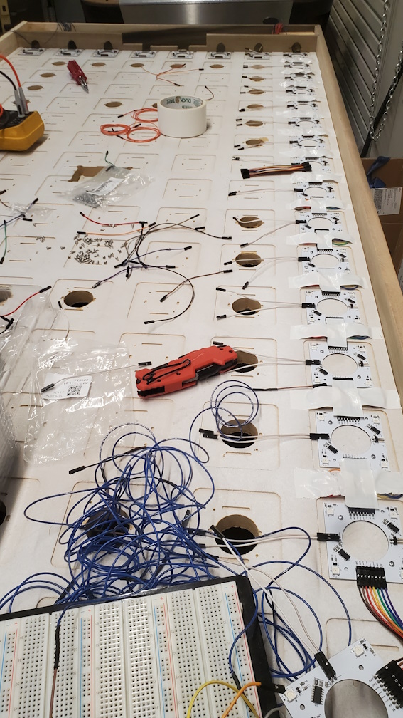 Figure 1: Early stages of assembling the LED matrix
Goal Chutes Are Difficult
As the table took form, I was finally able to slot in the test jig I mentioned in the previous report. After making a couple small adjustments to the dimensions, I was finally satisfied with the design. Due to the nature of 3D printing, the mounting tabs I mentioned previously were deleted to reduce the amount of support material and time required to print the chutes. Hot glue became our mounting hardware of choice after making this change. Although the design performed fine in tests, a problem was revealed once placed into the goal slot of the table. In some rare cases, the puck can become stuck in the goal chute; this requires the user to hit the top of the goal to dislodge it. The goal chute design was made more spacious to eliminate the possibility of the puck getting stuck. Since 3D printing is time consuming, the fixed design and the lower portion of the chute were not printed in time for our final demo, and there seems to be little chance of the team addressing this issue.
Designing Various Plastic Parts
To nicely mount the PCB and the power supply to the underside of the table, I quickly designed a couple of mounting brackets. The night before our final demo, I also designed a pusher for the players to strike the puck with.
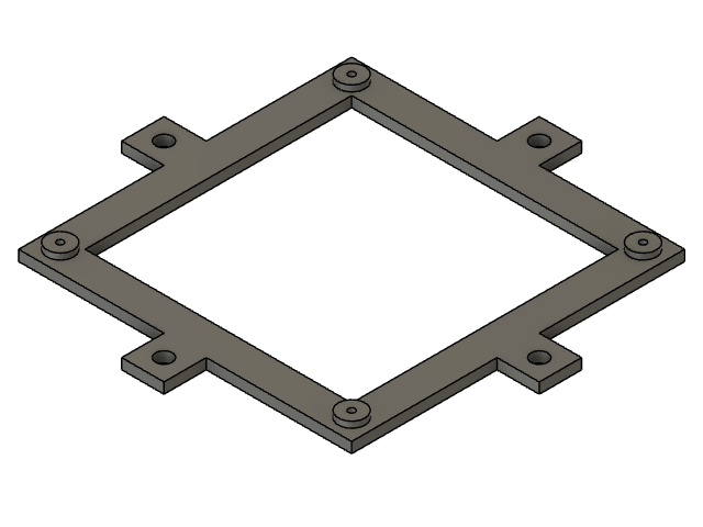 Figure 2: PCB mounting bracket
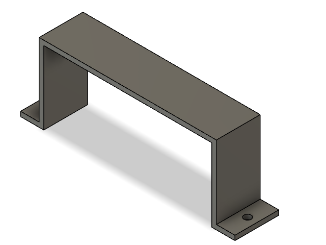 Figure 3: Power supply mounting bracket
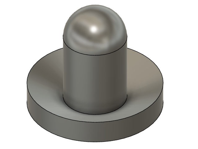 Figure 4: Simple pusher
Firming Up Firmware
My only big task with firmware this week was to implement the idle state that our table enters upon powering on or finishing a game. The two components to this are the menu system and the idle animation. I’ve prototyped the menu system in the past, but I started from scratch this time to make sure it was written with our current firmware in mind. It includes configurable options for maximum score and LED brightness. The idle animation is an eye-catching rainbow gradient flowing across the table.
Figure 5: Idle animation
Next Steps
The Spark Challenge is next week, so polishing up the overall experience of our project in preparation for that would be ideal. I will attempt to assemble a 2nd OLED display, and install it if assembly goes fine.
Week 13
Date: 11/17/2023
Project Hours Since Last Report: 11
Cumulative Semester Project Hours: 139
Description of Project Design Efforts
Goal Chute Revisions
A few revisions were made to the goal chute design over the course of this week. I extended the puck entry slot out into the goal to meet flush with the acrylic. After considering several ideas, I decided on a couple points to put mounting tabs that will secure the chute to the table. I took inspiration from the very first iteration of the goal chute and made the exit of the chute less inviting for hands to be inserted into. Lastly, I implemented feedback from Trevor by making the retrieval area deeper to securely hold the puck.
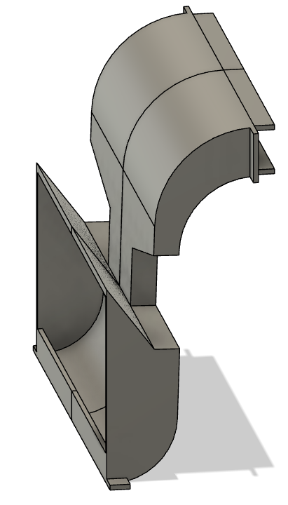 Figure 1: Latest revision of the goal chute design, featuring all previously mentioned improvements
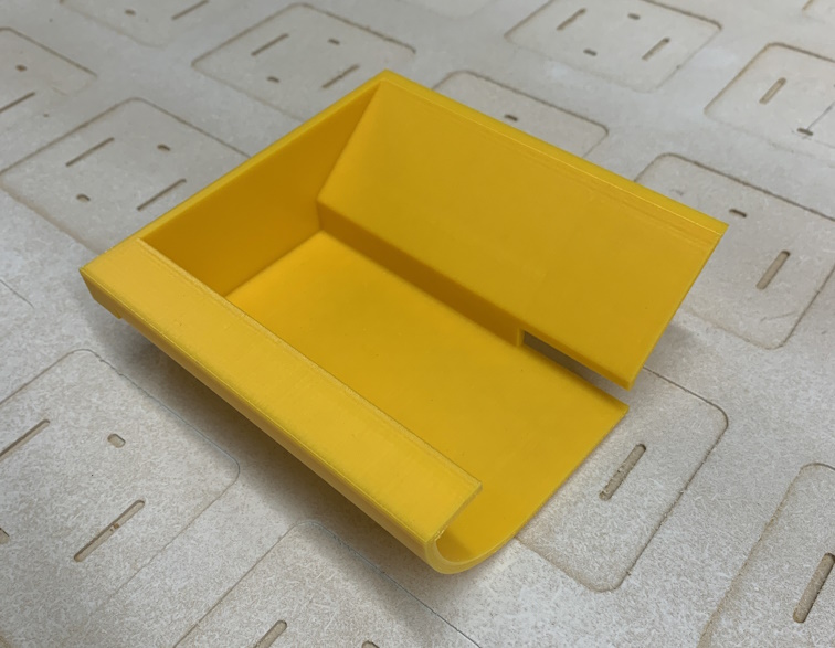 Figure 2: 3D printed portion of the goal chute for testing
Table Construction Continues
Over the weekend, I paid a visit to Menards to pick up some adjustable feet for the table. Keeping the table level no matter what surface it’s placed on is key to the quality of gameplay, otherwise the puck will continually drift towards one side. After drilling 4 holes and hammering the T-nuts into the bottom of the legs, I screwed the feet in and attached felt pads to them.
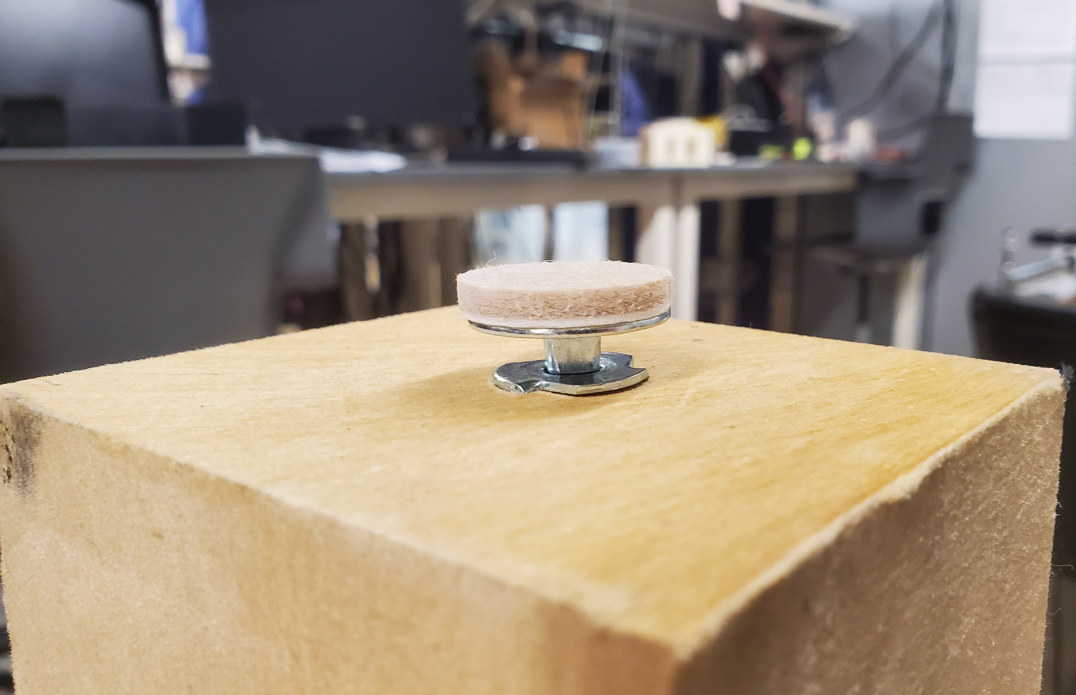 Figure 3: Adjustable foot attached to a table leg
In this week’s lab session, I worked with the team to test-fit the MDF into the table by placing the support planks in and laying it on top. Fitting the MDF proved to be impossible at first, and upon measuring we realized that it was an inch too long. Trevor and I carried it down to the sub-basement machine shop for it to be trimmed with a circular saw. In spite of this, the MDF was still barely too long. Some rough filing and dremeling took place, and then the MDF finally fit into the table. With the MDF in place, we confirmed that the play surface sits at the correct height.
Later in the week, some of the team oversaw our acrylic sheet being cut and drilled at BIDC. Once it was brought back to the lab, it also did not fit into the table as intended. I, with Trevor’s help, used a plastic-cutting dremel bit to trim an eighth inch off one end of the acrylic. After a lengthy session of adding additional support beams to the table’s underside to compensate for a warped board, the acrylic was properly fitted. I worked briefly with Ben and Alan to test the airflow properties of the table by taping up air leaks and sliding the puck around. Initial results were mixed, as we are still fighting against pressure leakage in a few areas. The acrylic flexed upward in the middle when air was turned on, and airflow reduced noticeably when the flex was corrected. As a result of this, we plan to increase the gap between the MDF and acrylic to allow for better airflow.
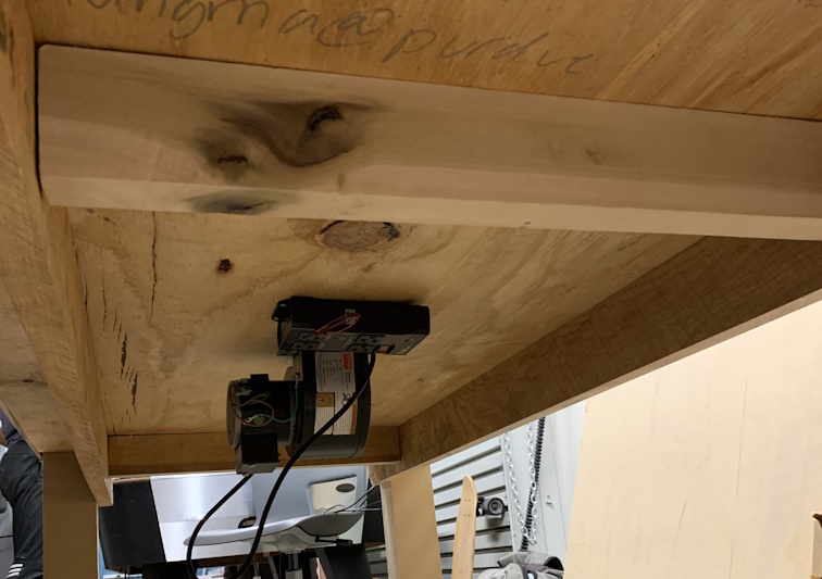 Figure 4: Underside of table with added supports visible
Next Steps
In the next couple of days, I plan to design a test-fit jig for the goal chute. This will allow me to test the fitment of the chute without needing to print the entire piece. I will be completing our project’s user manual very soon. Finally, the table’s construction will continue at an urgent pace.
Week 12
Date: 11/10/2023
Project Hours Since Last Report: 13
Cumulative Semester Project Hours: 128
Description of Project Design Efforts
Main PCB Testing and Verification
With all of our hardware finally in hand, this week’s important task was to finish assembling the main PCB. Aside from the task of physical assembly, which I was not directly hands-on with, PCB assembly also requires testing each functional block on the board after it is put together. I worked together with Trevor to develop simple functionality tests for the various hardware features as Ben was assembling the board. By the end, we verified that all the hardware components work with our firmware drivers that were originally written for the Nucleo prototyping board. From this point on, all firmware development will take place within the firmware-pcb workspace of our public respository. We are planning to remove the firmware-nucleo workspace once the main PCB is mounted to the table and connected to all external hardware.
Large Strides in Table Construction
With the point that our firmware and electronic hardware reached in the first half of the week, our primary avenue of progress then became table construction. We decided that creating supports for the MDF and putting legs on the table would be straightforward objectives to achieve. We started by cutting our leftover panel of MDF into 4 properly sized pieces; they will hold up the large MDF panel and form the walls of the internal air chamber. We also cut 2 smaller pieces that allow us to adjust the overall size of the air chamber independently from the supports. The table legs were formed from a large block of wood that Trevor and Ben identified earlier in the week. It was challenging to heave the immense block onto a cart and wheel it up to the bandsaw for cutting. Once there, it took 4 sets of hands to lift the block and feed it through the bandsaw. The first cut was just to bring the block down to a manageable size, as we only needed less than half of its total length. From there, we cut off several 30”×4”×3.5” posts to serve as table legs. Afterwards, I helped carry our various pieces of wood back to the lab where the rest of our table now resides. We came back later that day to attach the legs and finally get the table standing on its own. Through the use of a drill, jigsaw, hammer, and chisel, we cut holes up through the table’s corners, slid the legs through, and drilled screws in from the outside to attach them. Miraculously, the table stands sturdily with no wobbling at all despite eyeballing the leg attachment positions.
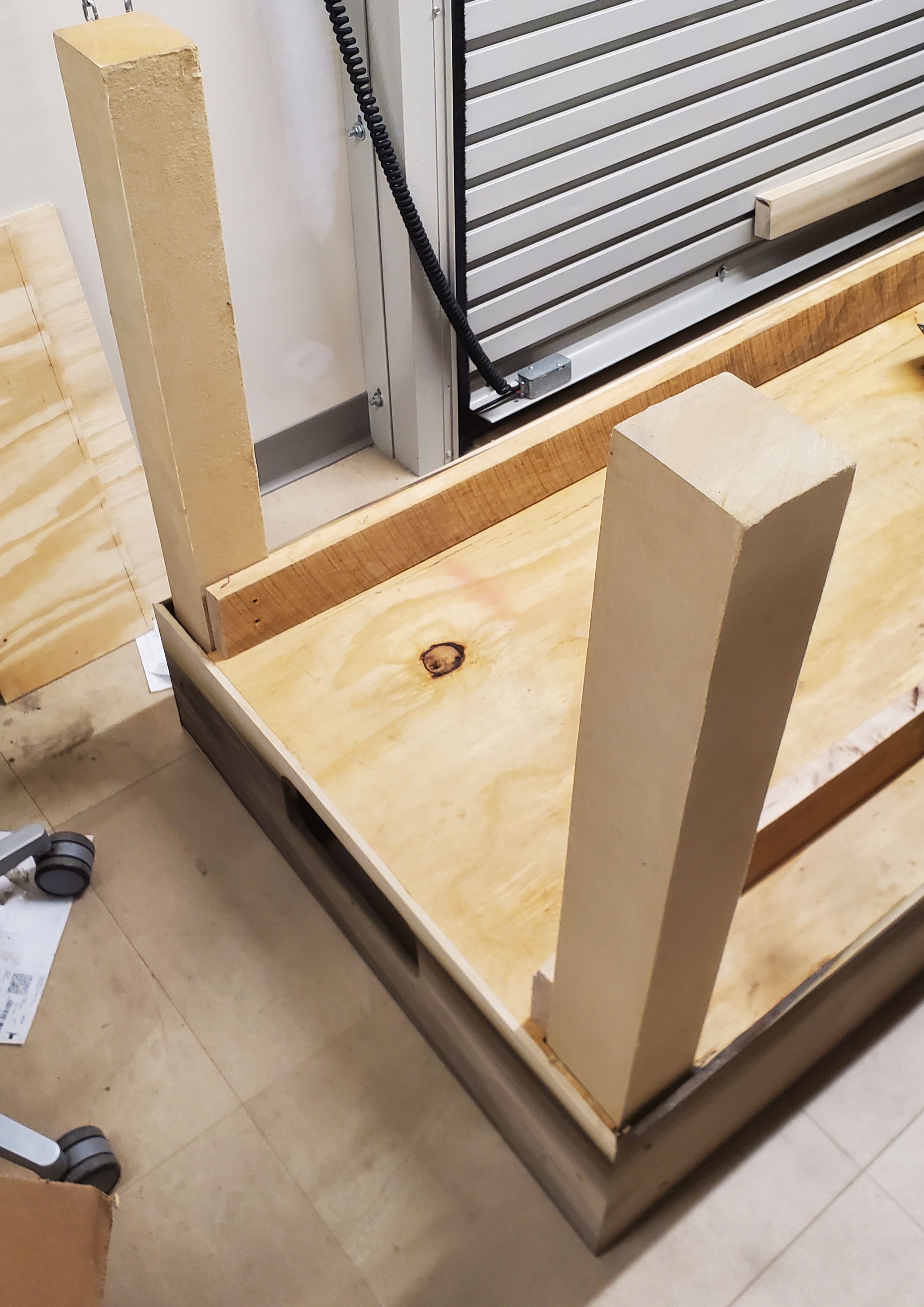 Figure 1: Table legs attached to our upside down table
Designing a Goal Chute
Although the bulk of our mechanical design effort is carpentry-related, there is an element of the table that requires some special attention. The chute that takes the puck from the goal, through the LDR circuit, and out the exit must be basically infallible. Getting a puck trapped in the mechanism would severely harm the user experience, so I designed the goal chute with this in mind. The three major elements are the rotator, funnel, and exit slot.
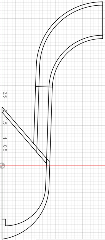 Figure 2: CAD sketch of the goal chute’s side profile
The curved upper portion is the rotator; it turns the puck vertical and confines it to minimize the chance of the puck wobbling and becoming stuck. The central portion is the funnel; it brings the puck inward to a channel slightly wider than the puck itself. This is where the LDR goal detection circuit will be mounted to. The bottom portion is the exit slot; the user will simply retrieve the puck from here after a goal is scored. The figure shown above depicts the second major revision of the goal chute. The first iteration was largely the same, except the funnel wasn’t tilted and the exit slot was shaped differently. The second iteration was also made to be modified easier by making use of constraints instead of “hard coding” dimensions into the design.
 Figure 3: 3D CAD rendering of goal chute in Fusion 360
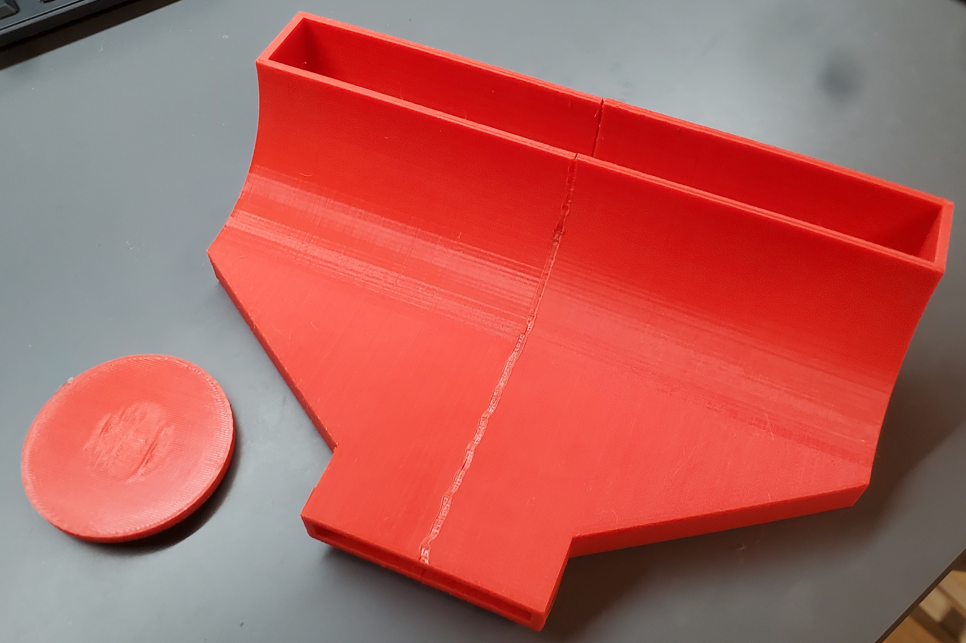 Figure 4: 3D printed upper portions of the first design iteration, courtesy of Ben
Next Steps
Next week will see the continuation of our focus on table construction. I plan to be involved in mounting components to the underside of the table and routing cables between them. I will also be searching for adjustable feet for the legs. I do not anticipate there being much movement on the firmware side of things, but some small adjustments may come up throughout the week.
Week 11
Date: 11/3/2023
Project Hours Since Last Report: 9
Cumulative Semester Project Hours: 115
Description of Project Design Efforts
Revamped Firmware Workspaces
As integration testing nears, we will be focused on validating the functionality of our firmware as we move to the full-scale table. The most pressing target for us to hit is keeping our core loop execution time under 1 millisecond. Throughout development, we’ve made various judgment calls that hinge on the compiler performing specific optimizations on our code before it is run on the microcontroller. A prime example of this is division operations (x / y) being replaced by bit shifting (x >> z), where y = 2^z. For the purposes of debugging, we’ve been compiling our code without any optimizations up until now. Since runtime debugging will continue to be a valuable tool in the future, I left the existing Debug mode intact and created a new Release mode. This mode enables full compiler optimizations on our code and results in a considerable speedup. Although it would be nice if Release mode wasn’t required for our firmware to function, it may become a necessity as we increase to full-scale.
Last week, when making our final Digikey order, we discovered that the microcontroller we intended to use (STM32U585) was out of stock. Fortunately, the nearly-identical STM32U575 that we already use on the Nucleo prototyping board was in stock. After a quick check to ensure identical pinouts and functionality, we made the choice to switch. Due to the way STM32CubeIDE projects work, this change necessitated recreating and configuring the firmware project for the new microcontroller. I also used this process as an opportunity to bring the project up-to-date with configuration changes made to the Nucleo project over time. Reassigning and naming each of the 100 pins was a very manual task, but it went by fast since I’ve done this a few times already. The aforementioned Release mode was introduced to the project at this time as well.
Miscellaneous Code Adjustments
Over the course of this week, Alan has submitted several small changes to our firmware for review. These have mostly been focused on renaming certain variables and constants, but also preparing for upcoming changes as well. As I reviewed these changes, there were several instances where I provided feedback or suggested modifications. The most impactful part of these overall adjustments has been to remove the LED matrix interleaving that I implemented last week. Keeping the data interleaved makes it harder to process and modify in an optimized way, but upcoming changes will require it. Ultimately, we do not solve any performance bottlenecks by interleaving the data, so it isn’t a huge loss to remove for the sake of making larger gains elsewhere. Several scattered changes have been made to the code since interleaving was introduced, so removing it wasn’t as simple as reverting a commit. Manually removing it gave me the opportunity to clean up some portions of the LED matrix driver at the same time. To test these changes prior to submitting them, I wrote a piece of test code to show a rainbow gradient on the LED matrix. Since we haven’t finished assembling all of our sensor PCBs, I tested with two half-rows of boards that were already set up.
Figure 1: Test gradient applied to LED matrix to validate functionality
Relocating The Table
Late in the week, Trevor and I wheeled an empty cart to the Bechtel Center to fetch our table and bring it back to the lab. We also removed the various clamps that had been attached to it and cleaned up the area it had been sitting. The most intensive portions of construction have been completed, so we feel confident in continuing to work on it at our lab station. The added benefit to this arrangement is that we can work on it whenever we want, instead of making timed reservations for equipment at the Bechtel Center. The half-mile journey back to BHEE was slow due to our cart not being well-suited for the rugged streets of the Purdue campus.
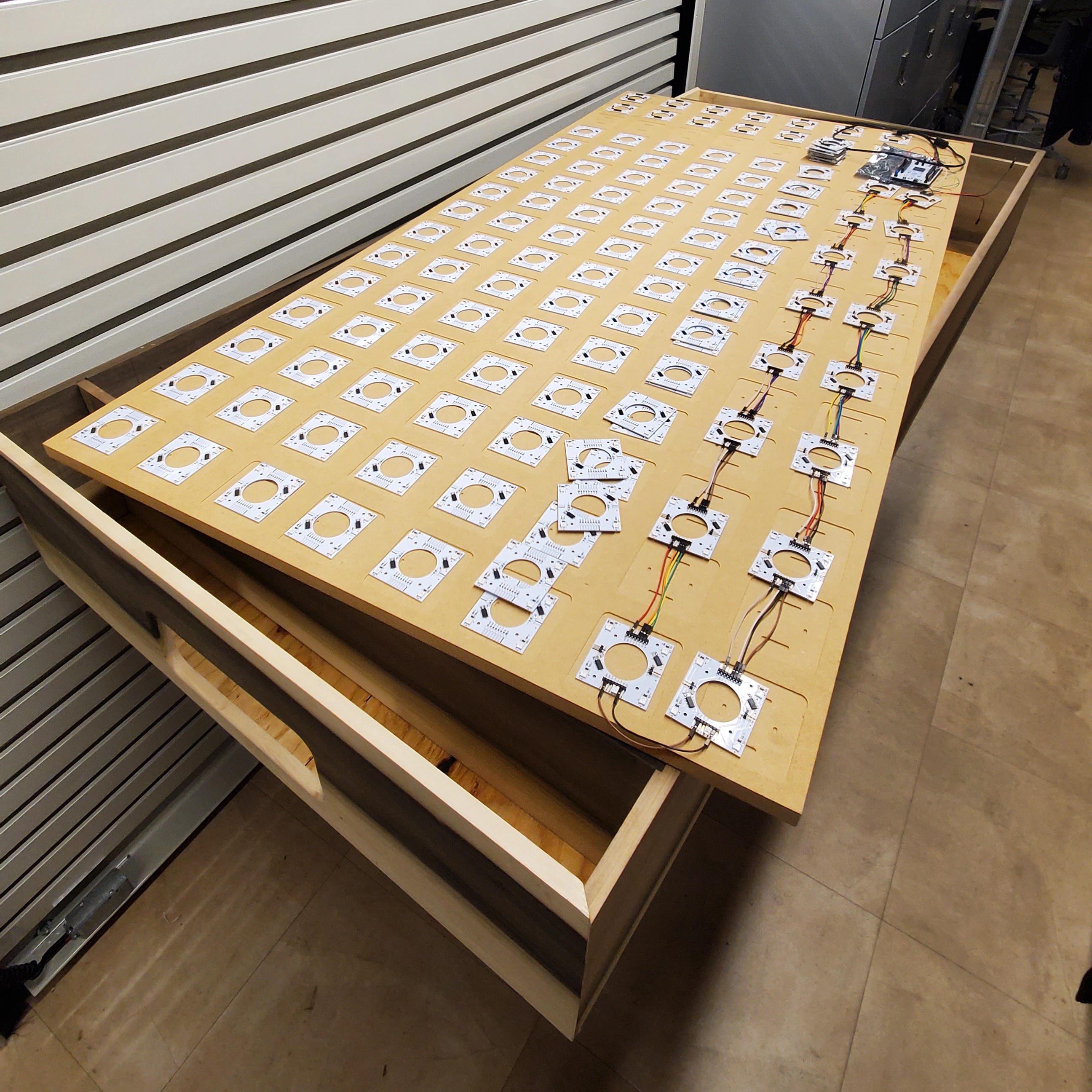 Figure 2: Two pieces of the table reunited after relocation to the lab
Next Steps
The thousands of wires needed to connect the sensor PCBs together will arrive early next week, so I plan to connect those as the boards are assembled. The rest of the team will be working on contributions to the firmware next week as well, so I look forward to reviewing those as they’re developed. There is still plenty to be done with constructing the table, so I’d like to make significant progress in that area soon.
Week 10
Date: 10/27/2023
Project Hours Since Last Report: 10
Cumulative Semester Project Hours: 106
Description of Project Design Efforts
Rotary Encoder Button Debouncing
Since Trevor finished developing the goal detection driver earlier this week, I decided to take another look at the encoder driver for the sake of consistency between them. Our rotary encoder hardware contains a push button, and as far as our firmware is concerned, the goal detector essentially functions as a light-activated button. The goal detection driver uses software debouncing to detect a goal once the signal has been low for several milliseconds consecutively. I copied this same functionality over to the encoder driver, and removed the external interrupts that we had previously been using to detect button pushes. I had to redo the button polling logic to accomodate this new approach, but it eventually worked as expected. After putting the code up for review, I became aware that we will have hardware debouncing for the button on our PCB. This negates the requirement to have software debouncing, and meant that changing our approach for the encoder driver was no longer necessary. I decided to close the review, since having such close consistency between the drivers’ functionality wasn’t very important in this instance.
Quad-Channel LED Matrix Optimization
Around the middle of the week, Ben brought up an idea for further improving our LED matrix driver, on top of what I implemented last week. Instead of keeping the data for each channel separated and driven by separate DMA transfers, we could carefully interleave the data into a single stream that one DMA transfer can handle. The benefit to this approach is that it slightly reduces the CPU overhead for updating the LED matrix, as we are only configuring and initiating one DMA transfer every time instead of four. Uncovering a way to accomplish this was challenging at first, as there were no readily available ways to configure the DMA transfer to handle interleaved data in this manner. Back when I was transitioning our firmware to the new microcontroller, I noticed a confusingly named DMA “burst” feature for the microcontroller’s timer peripherals. As it turns out, this was the key to unlocking the exact functionality I needed. This feature enables DMA to write to any number of contiguous timer control registers on a single transfer request, including those that control our LED matrix data transmission. All that I needed to do from here was retool the LED matrix driver to organize the outgoing data in the correct order. These changes can be viewed on our public repository.
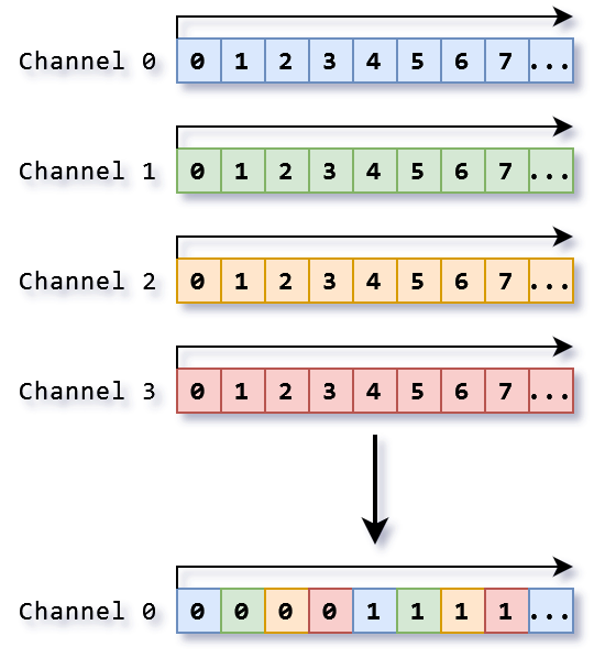 Figure 1: Graphical representation of old and new methods for transmitting LED data on multiple channels
Firmware Cleanup
After looking over our firmware over the past couple weeks, I thought of a couple larger-scope adjustments to make in the future. Now that all of our drivers are implemented and the basis of our application structure is in place, I decided at the end of this week to implement the changes. The first and most wide-reaching change was to replace every instance of the uint8_t and uint32_t data types with uint_fast8_t and uint_fast32_t. When reviewing the recently implemented goal detection driver code, I noticed that Ben introduced the use of uint_fast32_t on a few variables. After some discussing, we decided that propagating this pattern to the rest of our code wouldn’t be a bad idea. There were a few places where I decided it was necessary to keep the original fixed-size data types for compatibility with external hardware (e.g. OLED display). The next change I made was to remove almost every instance of the volatile keyword. This keyword turns off certain compiler optimizations when applied to a variable, but going forward we’d like to have our code fairly tightly optimized. We were using it up until this point because our application structure wasn’t yet well defined and utilizing it may be necessary in some cases. Now that we have a better idea of how many interrupt routines there are and what their individual priorities are, making decisions about the “interruptability” of sections of our code is much easier. volatile only remained on one variable, which keeps track of the realtime passage of milliseconds in response to a high-priority timer interrupt. The rest of the changes I made were minor; I focused on cleaning up formatting mistakes and keeping consistent implementations between similar driver code. Just prior to the end of the week, Alan submitted some revisions for review also, so I had the opportunity to provide a couple suggestions there as well.
Next Steps
As of the time of writing, our shipment of PCBs is due to arrive very early next week. Although our code has been tested on a handful of sensor PCBs linked together, we don’t know for certain that a full scale implementation works until we can test it. I plan to be involved in mounting and testing the full grid of sensor PCBs once they arrive. Provided that Trevor and Ben’s work goes well, I look forward to reviewing their code for the EEPROM driver next week.
Week 8 & 9
Date: 10/20/2023
Project Hours Since Last Report: 22
Cumulative Semester Project Hours: 96
Description of Project Design Efforts
Transitioning Firmware To New Microcontrollers
As mentioned in the last update, I began working on moving our existing firmware project to the STM32U5 family that we’ll be using for the remainder of the project. My initial steps towards this goal went by fairly quickly, as I only needed to set up peripheral configurations equivalent to our old project. Timers, SPI, and interrupts all function identically on the new hardware, but STM’s implementation of DMA has changed drastically. It seems to be almost entirely linked-list-based now, the available configuration and control registers are unfamiliar, and it has been renamed to GPDMA. DMA is vital to the operation of our LED matrix driver, so I knew I’d need to climb the learning curve for this sooner or later. Over the course of several days, I spent hours and hours fruitlessly attempting to coax the GPDMA system into working. Since this system is so new and currently has relatively little adoption, resources on how to use it are few and far between. STM has a series of guides, but they are rather surface level and make heavy use of their HAL. Since we aren’t interested in programming with the HAL, these guides were of questionable value in solving the issue. I eventually resorted to watching device register values with a runtime debugger, and managed to learn more details about GPDMA. Despite a few close calls where I nearly had things working the way I wanted, there was never an instance of all the pieces clicking into place at once and just working. I raised my concerns to the team on how our choice of microcontroller may not have been as ideal as imagined, since the newness of it was becoming an issue. Ben and I decided a new course of action would be best, given what we knew about the GPDMA system. The LED matrix driver will no longer continually transmit data in a loop, but instead it will be triggered whenever the state of the matrix changes. This simplified our interface with GPDMA, and allowed us to get the driver working again. Although this new approach uses more RAM, it will greatly reduce the active CPU load imposed by the driver. Rewriting the display driver was much simpler, but some small adjustments were still needed along the way. All of the aforementioned firmware development has thus far utilized the STM32U575 Nucleo board, as our Revision B PCB has not arrived yet.
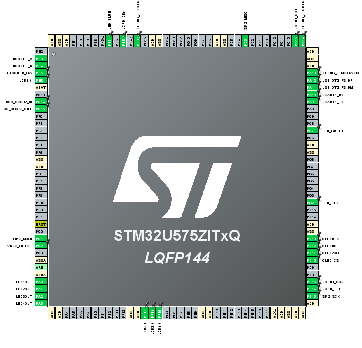 Figure 1: STM32U575 (Nucleo) IOC file showing a small subset of pins assigned
Rotary Encoder Driver
After successfully demonstrating a proof-of-concept for connecting a rotary encoder to our microcontroller, I decided to go ahead with developing a firmware driver for it. To take advantage of the “superloop” approach to our application’s central state machine, I designed this driver with a polling-based interface. The driver acts as a sort of latch, where it will accumulate inputs from the rotary encoder, and clear them once the state machine has polled the device. This behavior could lead to cases where the encoder is not being polled for a while, and when the state machine finally polls it, it will get very out-of-date information. I included a function to deactivate the driver for times when input is not needed. I created a snippet of code that shows a simple menu on the display, and reacts to the rotary encoder input accordingly. It was useful for testing the driver’s functionality, and may also be useful in the future when we implement a settings menu for the project.
Figure 2: Prototype menu selection showcasing rotary encoder functionality
Quad-Channel LED Matrix Driver
Near the end of this week, I refactored the LED matrix driver to support multi-channel output. This is made possible by employing 4 DMA channels to synchronously control 4 timer PWM output channels. Both revisions of our main PCB were designed with this in mind, so no additional effort is needed in terms of hardware. Driving the LED matrix on multiple channels allows us to update it much more frequently, since the total refresh cycle will now take a quarter of the time. Updating the LED matrix could end up being a bottleneck in the future, as it could potentially happen hundreds of times per tick when drawing animations to the matrix. I made sure to discuss with the team on how to approach this rewrite with performance in mind. Much of the computation related to the driver is faster to execute due to several of the numbers involved being powers of two.
Figure 3: Two LED matrix segments being driven on separate channels
Midterm Design Review Presentation
At the very beginning of week 8, I contributed to my portions of the team’s Midterm Design Review Presentation. I presented the prototyping progress, software development status, and timeline for the remainder of the semester. I enjoyed the opportunity to share my team’s work with a group of peer reviewers, and to see what my team had to share as well.
Miscellaneous Firmware Development
Over the course of week 9, I have been contributing reviews and feedback to the many pull requests that our firmware has been seeing lately. It has been an insightful process to see other’s approach to problems and learn from them more than I would’ve learned on my own. I have also gone back and made modifications to code I previously developed after seeing how new code written by the team was needing to interact with it.
Next Steps
As I understand it, table construction is closing in on completion, so I may assist in pushing towards that finish line within the next week. I will continue to test and make improvements to our firmware as new code is introduced. If our next batch of PCBs arrives soon enough, I would like to immediately start testing our firmware with the final hardware.
Week 7
Date: 10/6/2023
Project Hours Since Last Report: 16
Cumulative Semester Project Hours: 74
Description of Project Design Efforts
Display Driver Development
As the week began, our last batch of ordered components arrived at the lab. The first hardware I began prototyping with was our OLED displays. The initial work I did on this front, mentioned in Week 5, gave me a great head start. I did my best at the time to wrap my head around how writing data to the display works, but I knew it would be a process of trial and error once the hardware arrived. At first, I imagined this driver would behave similarly to the LED matrix, where it holds a buffer of the device state and writes it to the device repeatedly. Implementing this idea might’ve been possible, but due to the way updating pixels on the display works, I came to realize that it would be wildly inefficent and over-engineered no matter what. Updating the entire display takes at least 1 millisecond, which is longer than we’d like our application’s inner loop to take. Conversely, only updating portions of the display that have been changed would also introduce more overhead, to the point that pursuing this route is no longer worth it.
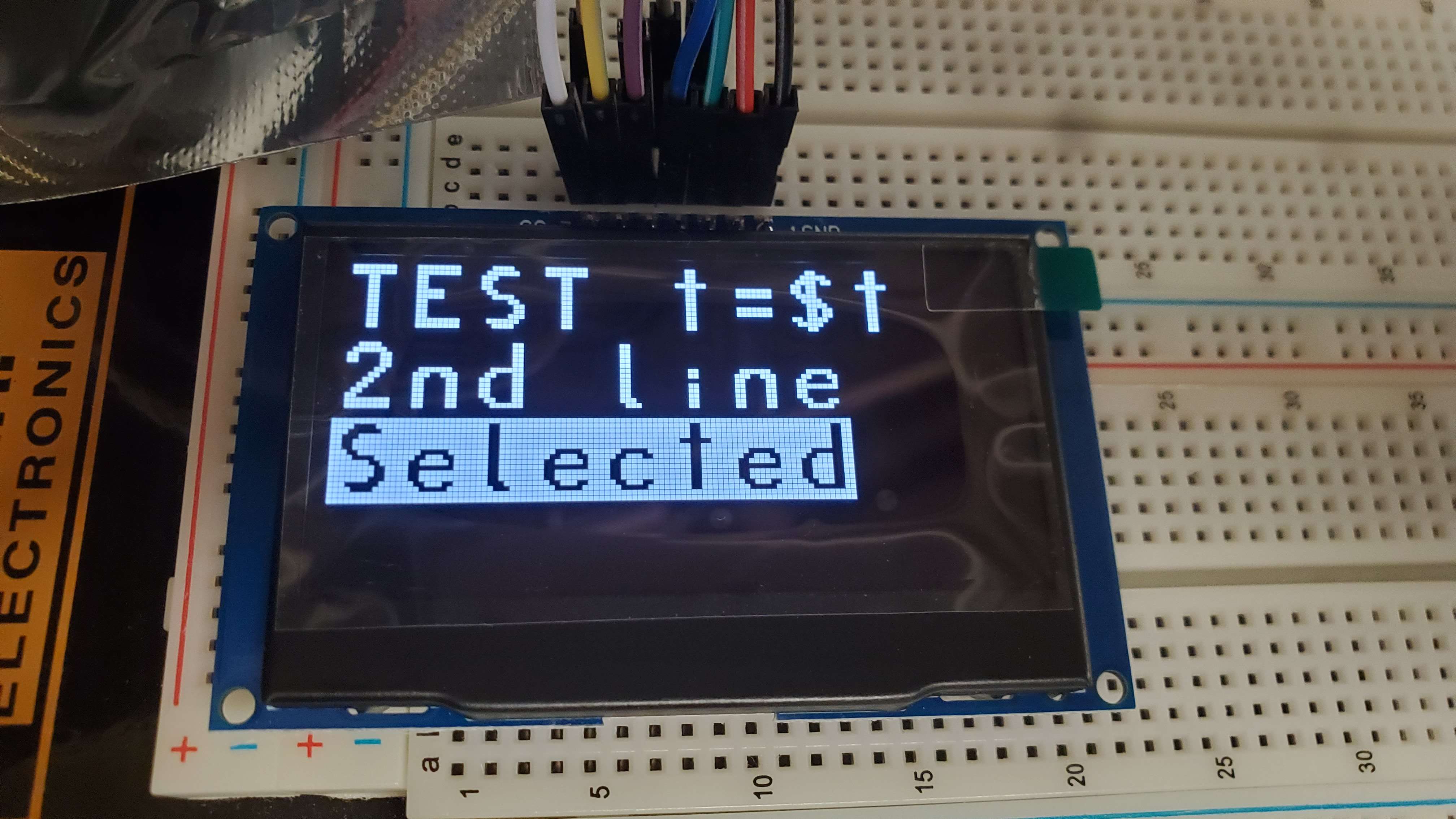 Figure 1: Early test of writing text strings to the display
Instead of writing the driver to be unnecessarily flexible and general purpose, I decided to focus on directly implementing the functionality we would actually need from the display. After discussing with Ben what we needed the display to accomplish, I decided to implement two different functions for drawing to the display: text strings and score tracking. Shown above is an early test of using the display to show multiple lines of text. To accomplish this, I developed a quick-and-dirty C# script that loads a PNG file containing the “font” and translates it to a byte array to be pasted into a header file in our firmware. From there, portions of this byte array can be sent directly to the display to render characters.
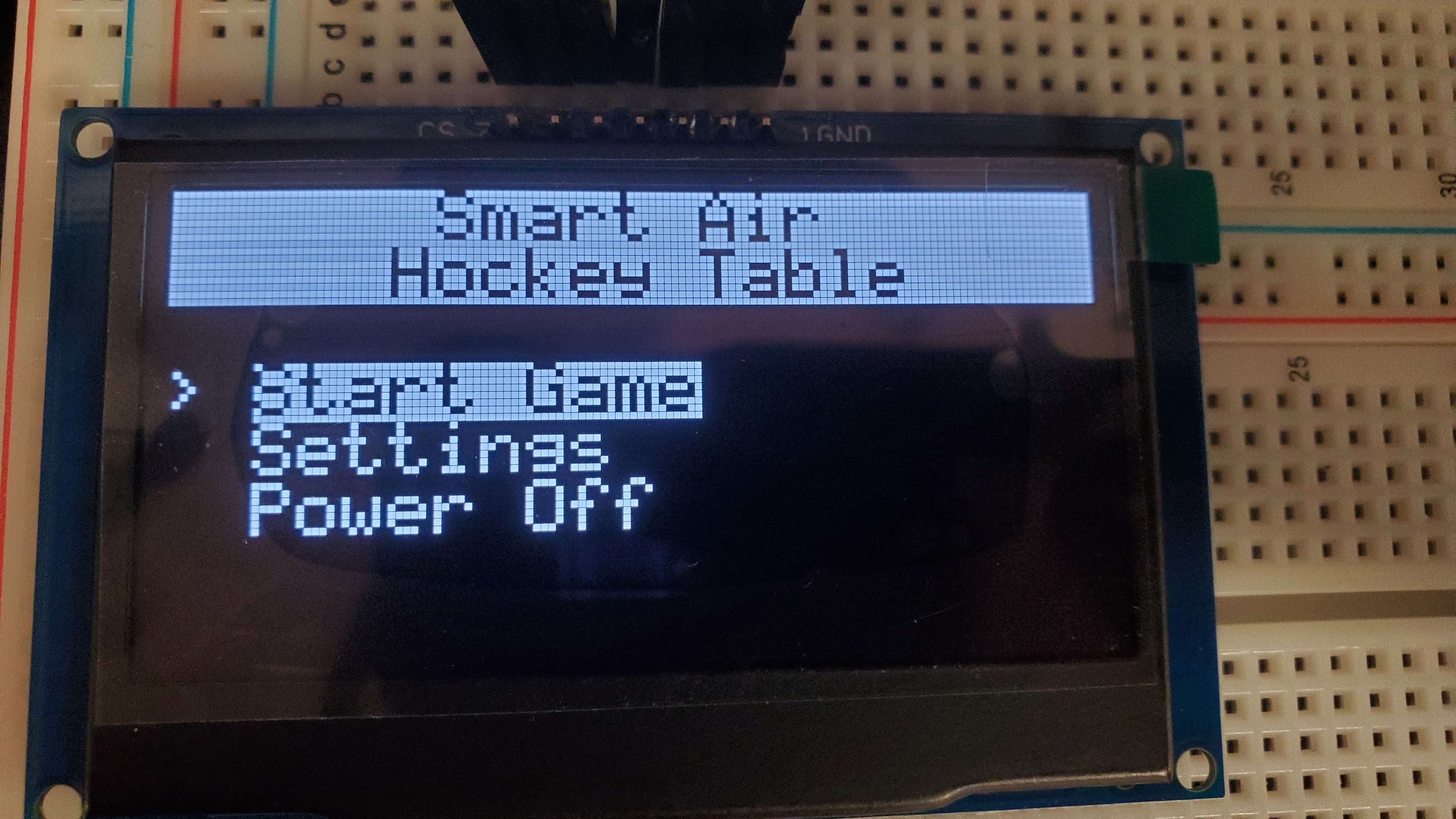 Figure 2: Prototype of the main menu display
The text strings functionality of the driver will be used to implement a main menu, which I mocked up a prototype of in Figure 2 above. Ben provided me with this smaller font to use, which looks quite sharp and allows us to fit 8 lines of 21 characters on the display. Showing text on the display will also be extremely useful for debugging in the future, as we won’t have to rely on extraneous devices being attached to the microcontroller.
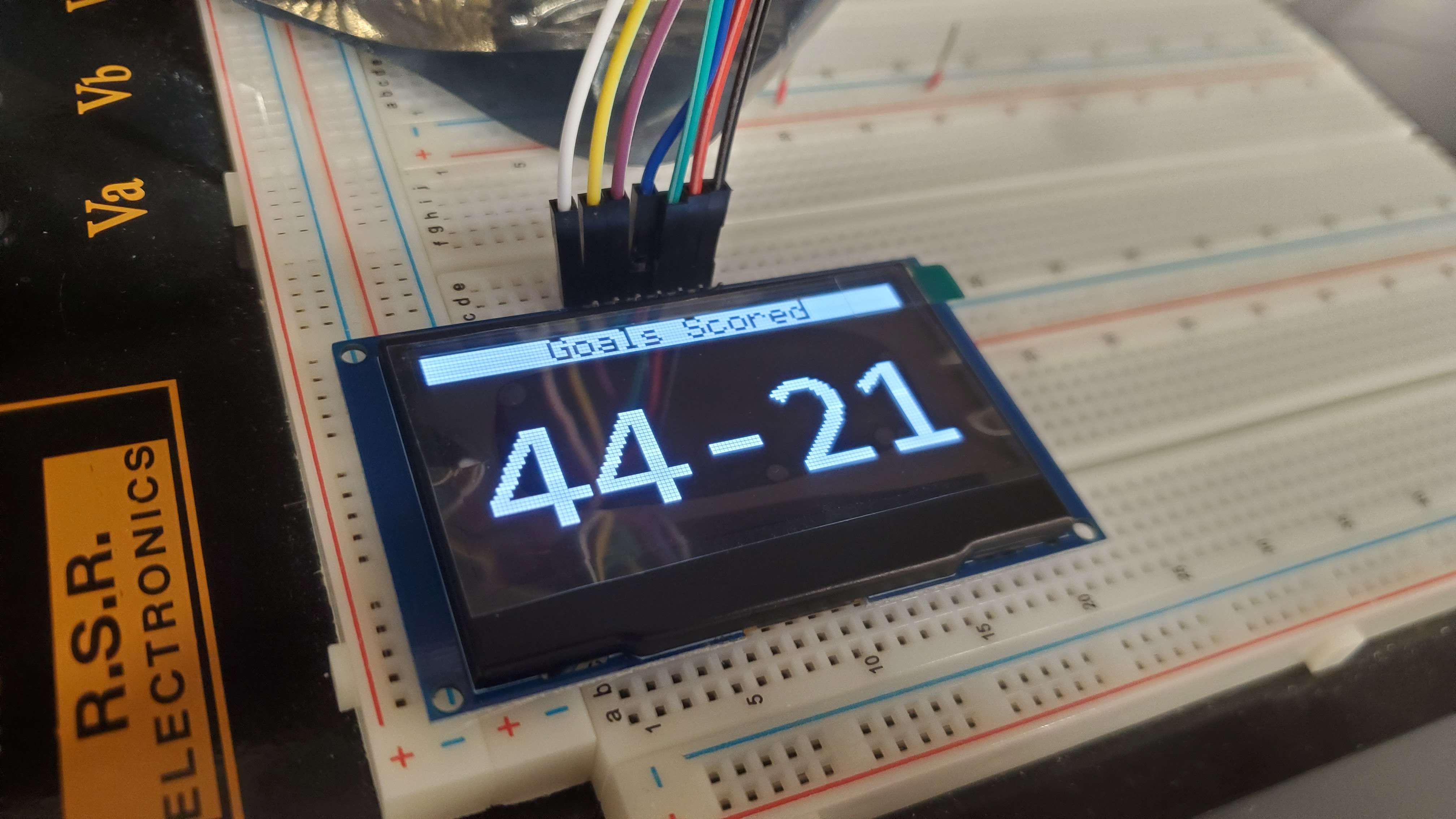 Figure 3: Prototype of the score tracking display
Displaying the larger characters required for the score tracking functionality meant that I needed to create another “font”. This time around, I created an image in Paint.NET and typed out each numeric character (and a hypen) in a monospaced font. The script I developed originally became useful once again to translate this image into a display-compatible format. The display driver supports drawing both separately and simultaneously to multiple displays, which will be required for both of the game’s players to see their score.
Updated Schematic Verification
Even though we just finished assembling Revision A of our microcontroller PCB and flashing a test program to it, we are already wrapping up design for Revision B. Ben finalized the latest changes recently, and I assisted in verifying them by filling up a pinout in STM32CubeIDE. This process allows us to be sure that the microcontroller pins we’ve assigned to certain functions are actually capable of providing that functionality.
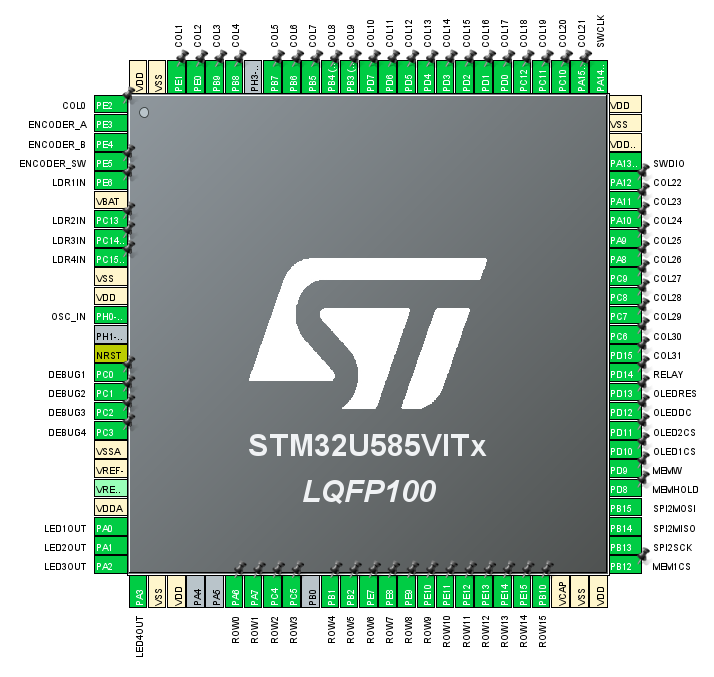 Figure 4: STM32CubeIDE IOC file showing a fully assigned microcontroller pinout
Visible in the screenshot above are all 100 pins of the STM32U585 microcontroller that we are using for the Smart Air Hockey Table. I gave a custom name to each pin as they appear in our PCB schematic. This also makes it easier to identify what external peripherals the pins are connected to at a glance.
Transitioning Firmware To New Microcontrollers
Up until this point, we have been prototyping our firmware on a Nucleo F446 evaluation board. Now that we have solidified our choice of microcontroller and received the hardware, I began the process of transitioning our existing codebase to it. To speed up our firmware development process, we also ordered a Nucleo U575 evaluation board that closely matches the specifications of the microcontroller we will use in the final design. Since it is technically a different chip, the same IDE project can’t be used for both. As a result, I will have to separate our codebase into two, and copy code between the workspaces whenever modifications made in one are needed in the other. At first, this sounded like it would be a large hassle to deal with. However, we will be prototyping new firmware solely with the Nucleo until our PCB design is finalized and assembled, so it won’t be necessary to constantly copy code back and forth. I opened an issue on our Kanban board to solidify our intentions for this process.
Continuing Table Construction
This week in table construction, Alan and I finished planing, jointing, and mitering the side and end boards. The staff at the Bechtel Center has been incredibly helpful throughout this process, and I’ve enjoyed learning how to operate the tools as we dive further into construction. We were nearly ready to make dado cuts and start gluing the pieces together, but the tools in the workshop were not set up for dado cuts at the time.
Next Steps
Since we will be the first team to present our Midterm Design Review Presentation, I plan to focus on completing my chosen sections over the next few days. Once that has concluded, I’d like to keep working on transitioning our firmware to the new microcontrollers and eventually testing the resulting code. Table construction will continue, and I may assist with testing the combined functionality of our sensor and microcontroller PCBs.
Week 6
Date: 9/29/2023
Project Hours Since Last Report: 14
Cumulative Semester Project Hours: 58
Description of Project Design Efforts
Provisional CAD Model of the Table
In last week’s report, I showed off an incomplete CAD model of our project. This week, I restarted the design from scratch, armed with new knowledge about our plans for the design. As I moved through filling in each component, I encountered a few important details that the team had not yet discussed in depth. Relaying these questions to the team proved to be very valuable, as we discussed our approach and weighed the best options for each issue. Although constructing this design was primarily a solo venture, I appreciated having the ongoing discussion with the team as I made progress. I call this design provisional because we are not actually using it as a point-by-point reference for physical construction. I created this design at the beginning of the week, and as the start to construction neared, Alan put together a design more closely based on the materials he had ascertained would be available.
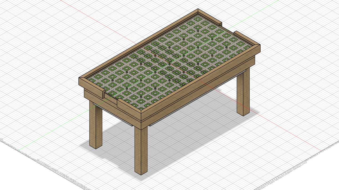 Figure 1: Final revision of provisional design for table construction
Pictured above is the state of the final revision I made to the provisional design. It includes all of our intended features, except for the goal assembly and score tracking displays. In total, I saved 13 unique revisions to this model over the past week. As I understand it, this design is still a useful point of reference for many unique details, but it no longer matches completely with our construction plans. I may bring the model up-to-date at some point prior to the conclusion of the project, but for now I will be leaving it as it is.
 Figure 2: Intended order of assembly for provisional design
As I neared the final revisions to the design, I created the animation shown above to illustrate the intended order of assembly to the team. Walking through this step-by-step process also gave me the confidence that the design could be physically constructed if we had the materials available. I enjoyed the opportunity to apply my prior experience with CAD software to learning Fusion 360, and I may find more uses for it in the future as well.
Software Formalization
This week, it was my turn to complete an individual assignment on behalf of the team. Just before I started working on the Software Formalization, I drafted several tasks on the team’s Kanban board. Each task I created was related to a specific firmware driver we will need to develop for our microcontroller. Within each task, I wrote a short list of physical requirements, such as hardware spec sheets, purchasing options, or details on connectivity. I also included definitions of the public interface for each driver. I then used these task specifications to write out the bulk of the Software Formalization, as many of our software components are just firmware drivers. Drafting the interface for the drivers provided an opportunity to expand my understanding of each component. This understanding will be useful in the future to better inform my decisions when developing the driver code. The state machine may serve as the central part of our software architechture, but I chose to focus more on drivers because the state machine can be depicted much better in a graphical form (provided in the document’s appendix).
Revising LED Matrix Data Pathway
Near the beginning of the week, I was looking over our proposed design for the sensor PCB and I noticed an issue with the peripheral connector layout. The connectors responsible for carrying LED matrix data across the system will be daisy-chained one by one, but there are a couple ways to achieve this. Shown in Figure 3 below are two alternatives; the upper section shows the revised plan whereas the lower section shows the connection pathway we originally had. Each PCB has two “in” connectors for LEDs, and two “out”. Arranging these in a snaking pattern saves us a lot of extra wire routing over the length of the entire matrix. We hadn’t ordered our first round of PCBs yet, so this issue was fixed before we sent off our design.
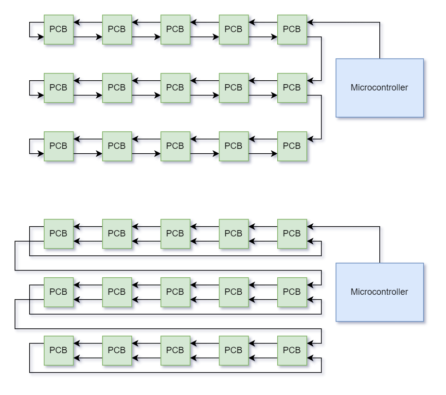 Figure 3: Diagram of alternatives for LED data pathway
Construction Progress
Later in the week, Alan and I reserved time at the Bechtel Center to make progress with constructing the table. By using the combination of a jointer, planer, and table saw, we gradually trimmed three poplar boards down to identical thickness and width. The wood we are using has a good-looking natural finish to it, which we were not anticipating. There is still plenty of work to be done until we have a full table, but this is an encouraging start.
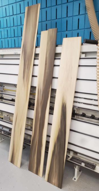 Figure 4: Nearly finished poplar boards to be used as sides of the table
Next Steps
Within the next week, I will continue to assist with constructing the table. As new hardware arrives, I would like to start working on prototyping and developing drivers for some of the simpler components. Our first round of PCBs are likely to arrive, and I will help test their functionality once they are fully assembled.
Week 5
Date: 9/22/2023
Project Hours Since Last Report: 10
Cumulative Semester Project Hours: 44
Description of Project Design Efforts
Initial Efforts on Table CAD Model
Despite high hopes for this week, I have not yet completed a designed model of our table. As I began drawing out even the simplest parts of the design, I began to realize just how many unknowns I was encountering. How much clearance do the PCBs need, what kind of spacers will we use, how thick will the acrylic be, on and on. Even still, I managed to create a mockup of the very top portion of the table. This was possible since it required no knowledge of the wooden component dimensions we’ll be using.
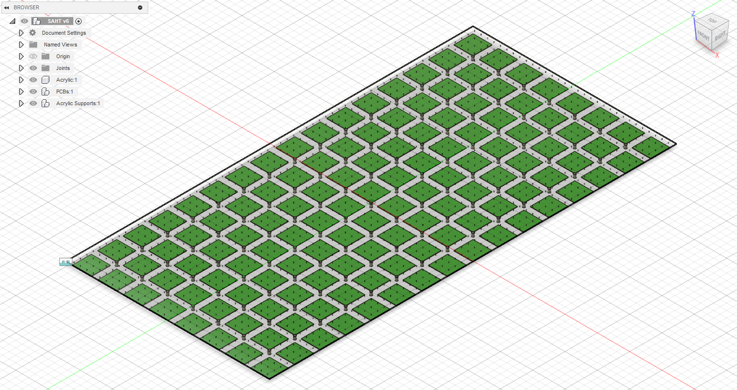 Figure 1: Current state of CAD model in Fusion 360
No matter how minimal or stripped down this design is from what it will eventually become, I still appreciated seeing it for the first time. I had the realization of just how many PCBs we’ll be assembling and connecting together, and it has further fueled my excitement for this project’s goals to come to fruition. Due to the number of unknowns that I was estimating rough values for, I elected to parameterize nearly every dimensioned value I possibly could, so they can be adjusted as we nail down real values. This had the added benefit of removing any magic numbers from the CAD model, which fits well with the programming mindset I’m used to.
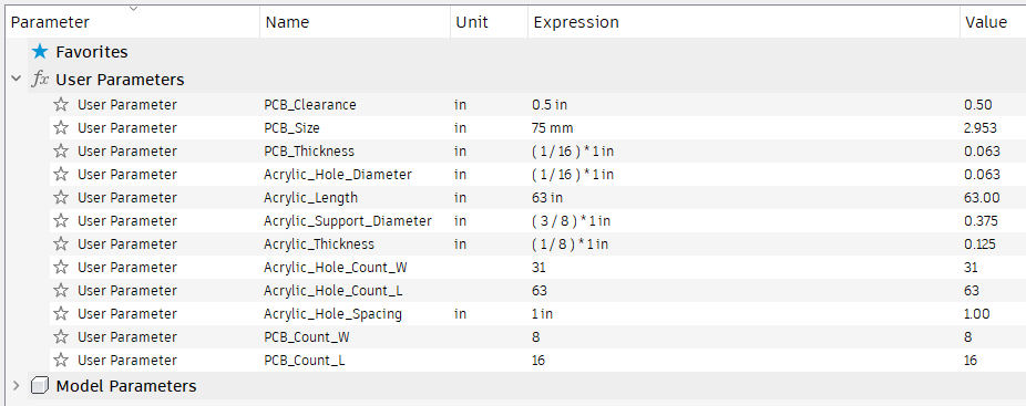 Figure 2: Configurable parameters that describe various dimensions of the design
Initial Efforts on OLED Display Driver
As the week moved on and I concluded that the time had not yet arrived to put my entire focus on designing the CAD model, I transitioned to a different task. Writing the LED matrix driver had been a fairly straightforward and rewarding endeavor, so surely writing a driver for the OLED display would be just as fun. The first major snag I stumbled upon was reacquiring the datasheet for the display we had previously used in ECE 362. Pasting the product code into Google yieled some results, but nothing that described the SPI control protocol in much detail. I eventually decided to search for the ECE 362 lab website and located their hosted copy of the datasheet. Once I had begun poring over the document and configuring our microcontroller’s peripherals accordingly, I arrived at another snag. Our prototyping device, the STM32F446 has a less sophisticated implementation of STM’s SPI peripherals, and can only be configured for transmitting 8- or 16-bit words. However, the SPI protocol for the OLED display requires us to send 9-bit words, which our microcontroller in ECE 362 was capable of. Although it meant that I was unable to test the driver at the time, the microcontroller we’ll use in our final design (STM32U585) does posess the needed capability. All of this became a moot point when we recently switched our choice of hardware for the score tracking display. We made the decision to utilize a full-pixel OLED instead of character-based, which had been under heavy consideration beforehand. With our choice of display hardware now finalized, I began distilling some vital details from the datasheet into a formatted document on our GitHub issues page. This was done with the intent to jumpstart driver development once the new hardware arrives.
Parts Procurement and Bill of Materials
Now that we’ve arrived at the end of week 5, the push to start purchasing hardware is stronger than ever. With Ben and Trevor making incredible progress on designing our two PCBs, we’re nearly at the point where ordering components is the next logical step. Over the course of the past few days, I’ve collaborated with the team on putting together our official procurement documents for submission as soon as possible. At this stage, we will be making orders from three separate vendors: Digikey, Amazon, and JLCPCB. Our process for appending components to the procurement form has largely consisted of sharing URLs back and forth and giving our thoughts on each option. I also held primary responsibity for transforming each decision into a properly formatted entry in the procurement spreadsheet. An exciting result of this process was the inclusion of an STM32U575 Nucleo evaluation board on our order form, which will allow us to prototype features for our microcontroller simultaneously while assembling our master PCB. Late in the week, I made an attempt submit our documentation for purchasing PCBs, but the recommended office (BHEE 140) is unreachable or no longer exists due to ongoing renovations. Instead, I will deliver this documentation to an alternate location in the very near future. Fortunately for us, we decided to work on the procurement document during the same week that the Bill of Materials assignment is due for submission. This overlap should make it trivial to fill in the required information for each of our components.
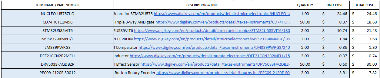 Figure 3: Current list of components to be ordered from Digikey, with part number and pricing info
Next Steps
Although this week consisted of a couple false starts on my behalf, I am hopeful that having nailed down several component choices at the end of this week will make future attempts at project design more fruitful. Early next week, I’d like to place orders for all the hardware we’ve decided upon, and possibly start assembling the parts that arrive before the week is out. I am especially excited to see our first batch of PCBs arrive and begin testing with them. In the near future, I will be participating in training at the Bechtel Innovation Design Center to obtain authorization for constructing our table at their facilities.
Week 4
Date: 9/15/2023
Project Hours Since Last Report: 13
Cumulative Semester Project Hours: 34
Description of Project Design Efforts
LED Driver Implementation
The visual aspect of our project will heavily rely on a matrix of individually-controlled RGB LEDs placed underneath a translucent play surface. On a technical level, we chose to achieve this by making use of WS2812-compatible LED hardware. It requires an 800 kbit/s data transmission rate from the hardware that drives it, so simple bit-banging will not suffice in our case. As I covered in last week’s report, I chose to drive the LEDs with our microcontroller’s timer and PWM generation peripherals.
My initial approach to this problem was to store a large array containing every PWM timing configuration required to transmit the current state of the LED matrix. From there, I used DMA to continuously stream the PWM timing configuration into the control register. Although this approach functioned correctly and was able to drive the LEDs as desired, the RAM usage was very inefficent. The design for our LED matrix contains 512 LEDs in series. For each LED, 24 bits are required to describe its set color. For each transmitted bit, a 16 bit control register must be populated via DMA. The combination of these factors means that the RAM usage requirement would rise to 24 kilobytes in a full implementation. In cases where we would like to store multiple “animation frames” of LED matrix data, the memory usage is prohibitively great.
Upon further research, I decided that storing a significantly smaller buffer would suffice, when given the proper design consideration. In its current iteration, the LED driver transfers PWM timing configuration from a buffer containing just two 16 bit values. In order to correctly set the values in this buffer, I make use of the DMA half transfer and DMA transfer complete interrupts to update the half of the buffer that is not actively being copied to the configuration register. Although this approach introduced new CPU overhead (in the form of the DMA interrupts), it reduced CPU overhead in a different area. In the prior implementation, calling the LED driver to update a color value required immediately translating it into the proper sequence of PWM configuration values. Now this process is taken care of by the introduction of the aforementioned DMA interrupts. An additional benefit to the new driver implementation is that the LED matrix state can easily be queried by the application, as it is now stored in raw RGB values instead of PWM timing data. The RAM savings for this approach are significant, now taking only 1.5 kilobytes (a 93.75% reduction). If a further reduction is needed in the future, this approach allows us to easily reduce the bit depth of the RGB color data without significant code modifications. The full driver code can be viewed in our open source repository.
Figure 1: Test pattern applied to our LED prototyping hardware by the latest driver implementation
Formalizing Main Application Architecture
While developing the LED driver, I was simultaneously organzing the structure of our firmware application. Although I made important steps toward this goal last week, there was still some smoothing of rough edges to do. The entrypoint for our main application is now in app_core.c, and my intention is that any additional files that support our application in a central manner be named with app_ prefix. A primary example of this is the debugging module I created (app_debug.c). At the moment, this module contains a function to print timestamped log messages to the integrated serial interface, but it will be expanded in the future to contain firmware debugging functions as needed. Obtaining an accurate timestamp for log messages necessitated enabling a hardware timer and writing a basic interrupt handler for it. As with driver_led.c, my goal is for all driver source files to be prefixed with driver_ as they are created for new hardware (such as small panel displays).
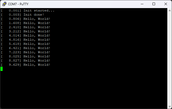 Figure 2: Demonstration of debug logging output from the microcontroller
In this week’s Component Analysis assignment, I was primarily responsible for analyzing our component choice for the LED matrix and the score tracking display.
Next Steps
Within the next week, I plan to fully design a CAD model of our table. This will be important as we prepare to construct the table, so that no guesses or assumptions are made throughout the process. Designing the table will also require me to research common dimensions for parts that it will be comprised of, such as plywood sheets, acrylic panels, and common sizes of wooden plank. Knowing these allows me to make the best decisions for designing the table right now, even if they may be adjusted in the future as we move into construction. I have already installed Autodesk Fusion 360 (on Ben’s recommendation) for this purpose.
Week 3
Date: 9/8/2023
Project Hours Since Last Report: 12
Cumulative Semester Project Hours: 21
Description of Project Design Efforts
3.3V to 5V Level Shifter Prototyping
As the week began, I was eager to start working with our LED hardware. The most immediate obstacle to opening an IDE and writing a driver was that our microcontroller operates on 3.3V logic, whereas the LED strip we have available runs on 5V. The “fastest-to-market” approach to solving this problem was to create a level shifter circuit on a breadboard. During a visit to the ECE shop, I was recommended to utilize a 2N7000 MOSFET to accomplish the voltage conversion. After researching some possible designs, I chose two to build and test.
The first of these designs is the simplest, as it only requires a 5V supply and features very straightforward connections. Source
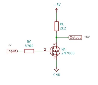 Figure 1: Circuit schematic of 1st MOSFET-based level shifter
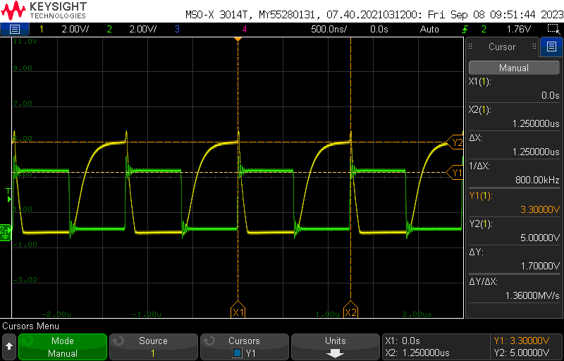 Figure 2: Oscilloscope output of the above schematic
From Figure 2 above, it can be observed that the rise time of the square wave is fairly significant compared to the wave’s period. This is undesirable as the timing requirements for the LED specification are fairly strict (less than a microsecond). The 800 kHz frequency of the depicted wave is important, as this is the data rate the LED specification requires, so testing at this frequency closely simulates the conditions the level shifter will be subject to.
The second design I constructed is also quite simple, but it requires a 3.3V supply as well as 5V. The design shown below was constructed once again with a 2N7000 MOSFET, as well as two 1 kΩ resistors.
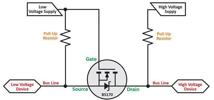 Figure 3: Circuit schematic of 2nd MOSFET-based level shifter
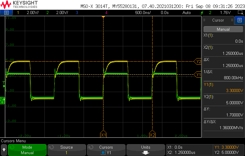 Figure 4: Oscilloscope output of the above schematic
The level-shifter design demonstrated in the figures above features a much improved rise time as compared to the prior design. I had initially constructed this design with 10 kΩ resistors, but the response characteristic had not improved significantly. Transitioning to a lower resistance proved to provide the performance I was hoping to see in the first place. I continued to utilize this design throughout the rest of the week as I moved forward to controlling the LED strip.
Software Reorganization and New Implementations
Before I dove fully into writing firmware to drive the LEDs, I decided it would be in the best interest of organization to decouple our code from that generated by the STM32 IDE. Not long after beginning this process, I had already run into a couple snags. The code generated to interface with the HAL (hardware abstraction layer) did not lend itself well to being used in places besides the main.c file. Additionally, I discovered that the HAL keeps track of its own state instead of relying on the built-in hardware registers, which introduces extra overhead that we’d like to avoid in the long-term.
I switched over our project, so now the IDE was generating “low layer”-based code, as opposed to HAL-based. This route felt similar to what I was accustomed to from ECE 362, and it allowed me to refer to the microcontroller reference manual more often. In the future, we may transition out of using any code generation, and rely fully on CMSIS headers and directly accessing device registers.
From this point, I researched how to set up a basic hardware timer and programmed it to output PWM on a GPIO pin. This was the first real step towards the eventual goal of implementing a LED driver in our firmware. The timing specification for our LED lighting hardware is functionally a PWM wave with a carefully controlled pulse width.
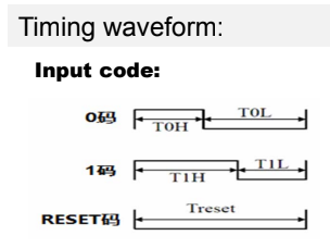 Figure 5: WS2812 specification timing diagram for sending 0 bit, 1 bit, and reset codes
In the following handheld video recording, I showcase my current progress on interfacing our microcontroller to the LED hardware we are prototyping with. The LEDs are toggled on and off at 2 Hz, and the associated PWM control signal can be observed on the oscilloscope display.
Next Steps
In the near future, I plan to implement and seek feedback from my teammates on a full-fledged LED driver. The driver will consist of a single source and header file, and I plan to make use of DMA (direct memory access) to feed the precise timing data to the PWM timer with minimal processing overhead. This will allow us to focus on more computationally expensive tasks in the future, such as ingesting and processing sensor data.
Week 1 & 2
Date: 9/1/2023
Project Hours Since Last Report: 9
Cumulative Semester Project Hours: 9
Description of Project Design Efforts
Microcontroller Software Setup
This week, I was primarily focused on setting up a software build environment for our main microcontroller, the STM32F466. I did this by installing the STM32CubeIDE and generating a straightforward test program. As Trevor has some prior experience with this software package, I worked alongside him to learn the various features and tools it has to offer. In tandem with setting up the build environment for software, I also began working with our microcontroller development board, and succeeded in flashing a functional test program to it. I took extra steps to ensure that the standard printf function works as expected, so now device logs can be viewed in a connected PuTTY terminal.
I felt these steps were important to complete as soon as possible, so we can focus on designing our software in the coming weeks. Throughout this process, I took care to collect any relevant datasheets or reference manuals I encountered. I uploaded them to our team’s shared file storage, so we can easily refer to them in the future. It is encouraging to see the hardware and software working together already at this early stage.
Team Assignments / Documentation
Within the first week, I collaborated with my team on our Final Project Proposal. Beyond filling in my info and delegated roles, I contributed by revising the drafted PSDRs to fit the proper phrasing (“An ability to…”), as well as reorganizing them for clarity and conciseness. During our meeting to collaborate on the Functional Specification document, I authored a Peripheral Hierarchy flowchart to visualize and clarify our intended design approach. It is my intention that this diagram be revised and expanded over time as our project has more details finalized.
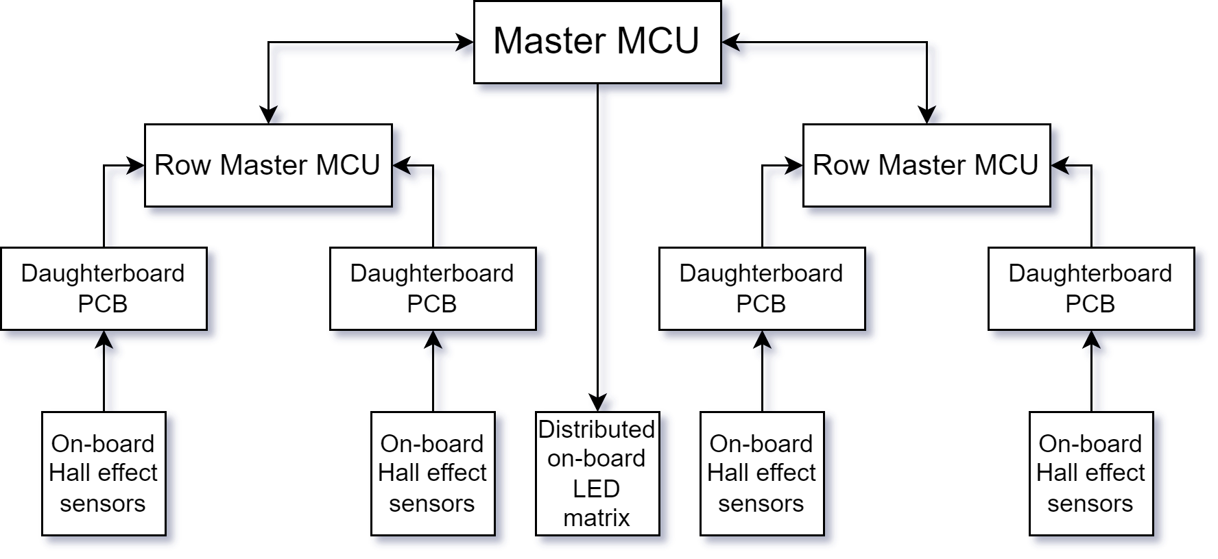 Figure 1: Provisional draft of project’s Peripheral Hierarchy
In regards to the aforementioned Functional Specification, I am currently documenting our project’s known computational and thermal/power constraints.
In the next week, I look forward to prototyping with hardware and determining the feasibility of our current design plans. I also plan to begin laying out the high-level design for our software architecture.