Progress Report for Alan
Week 14 & 15
Date: 2023-12-01
Week Hours: 50
Total Hours: 203
Description of Project Design Efforts
This was the last push for the demo, everything was finished in time for the final demo.
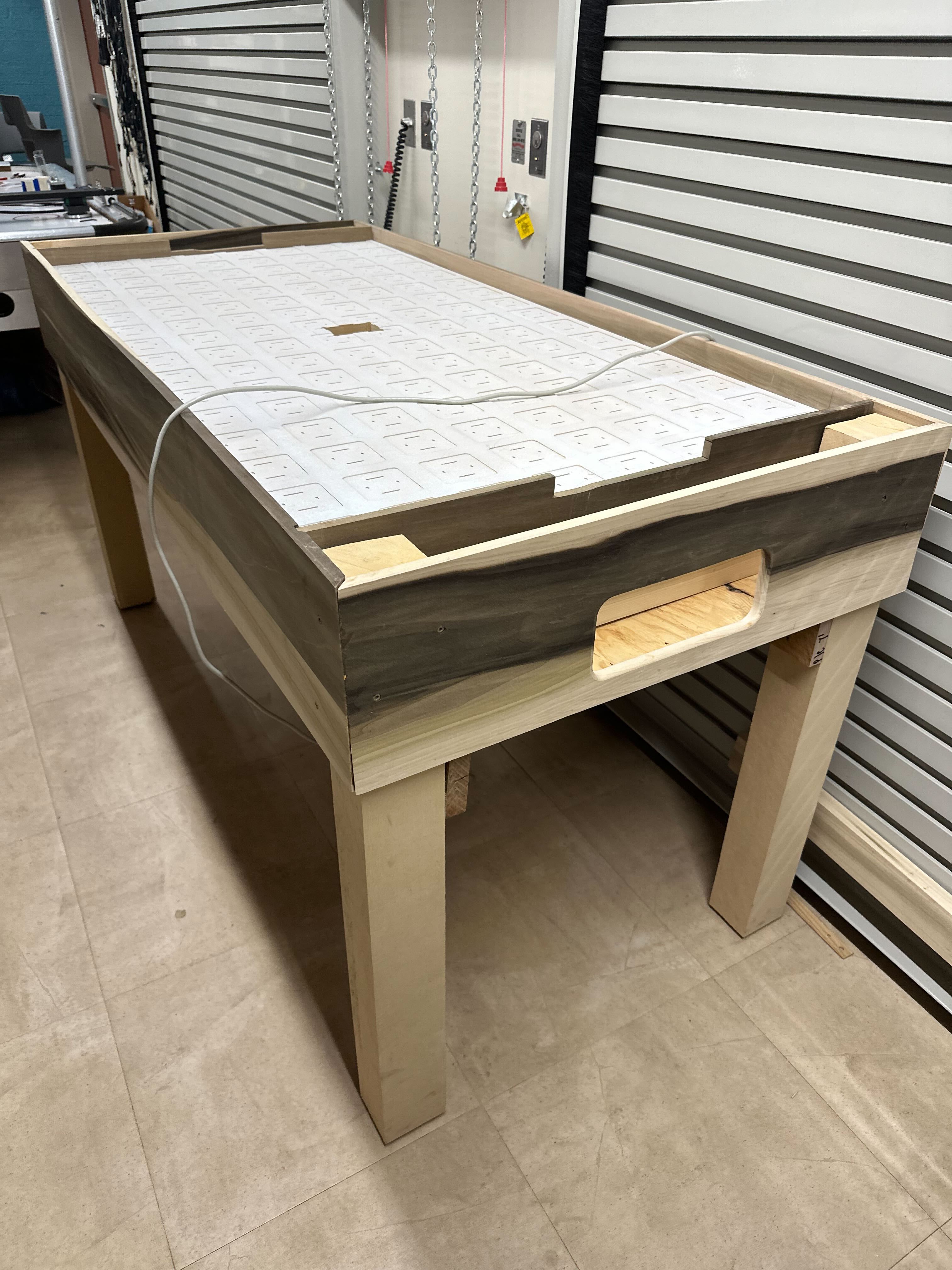
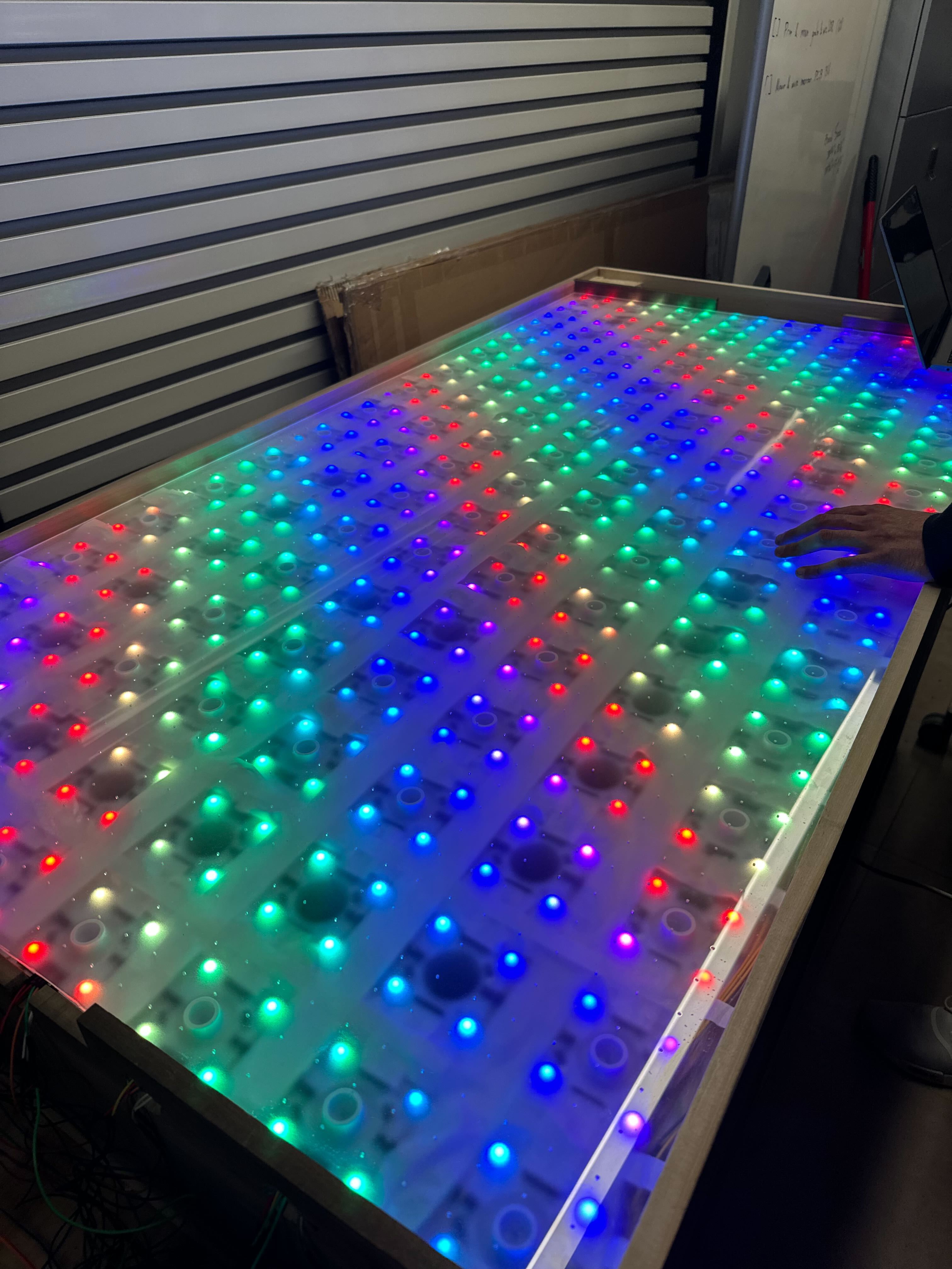
Finishing the Table
Basically installing everything on the table such as the wires and sensor boards. Once we got it all connected together, Will got a rainbow backlight going.
| Before | After |
|---|---|
 |  |
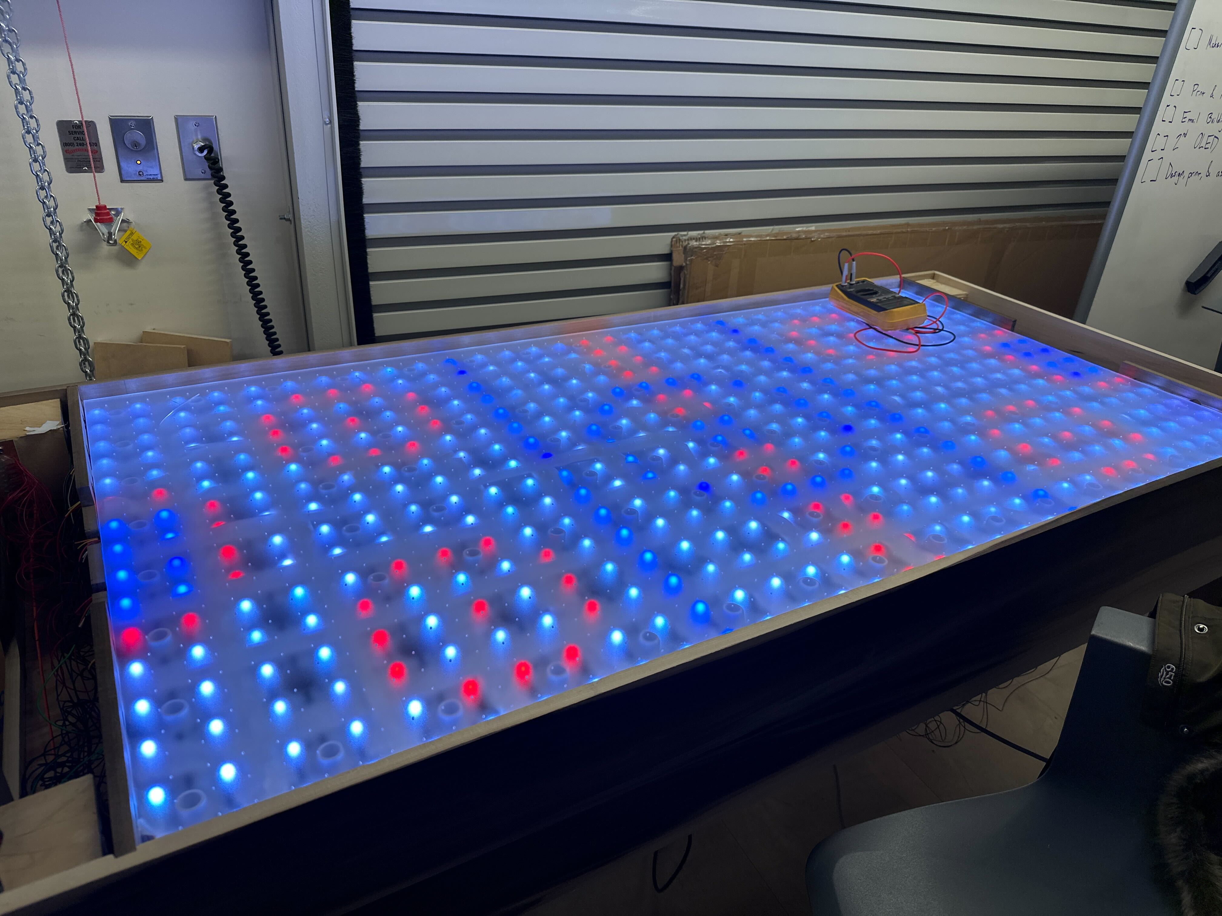
Setting up a Background
I played around with setting up a static background, below is the ice hockey design we tried but it did not look good. We ended up going with a solid background since that looked best.
Integrating separate components
I helped integrate the background with the encoder and OLED. It was rather simple but we discovered a few bugs and added some logic for the encoder to control the brightness.
Trail Animations
I worked on the logic that created the trail. It was a simple circular buffer. More work will need to be done so that it behaves as expected but it looks pretty good.
Next Steps
We have finished the demo. The remaining effort will be to clean up the resulting table for Spark challenge and all the deliverables left for the course.
Week 13
Date: 2023-11-17
Week Hours: 13
Total Hours: 153
Description of Project Design Efforts
This week I was mostly working on the mechanical things with the rest of the team. I am not so big with taking pictures but I will attach those that I have taken.
Cutting the MDF to fit and add a hole
Me and Ben made sure to get the MDF to fit in the table properly.
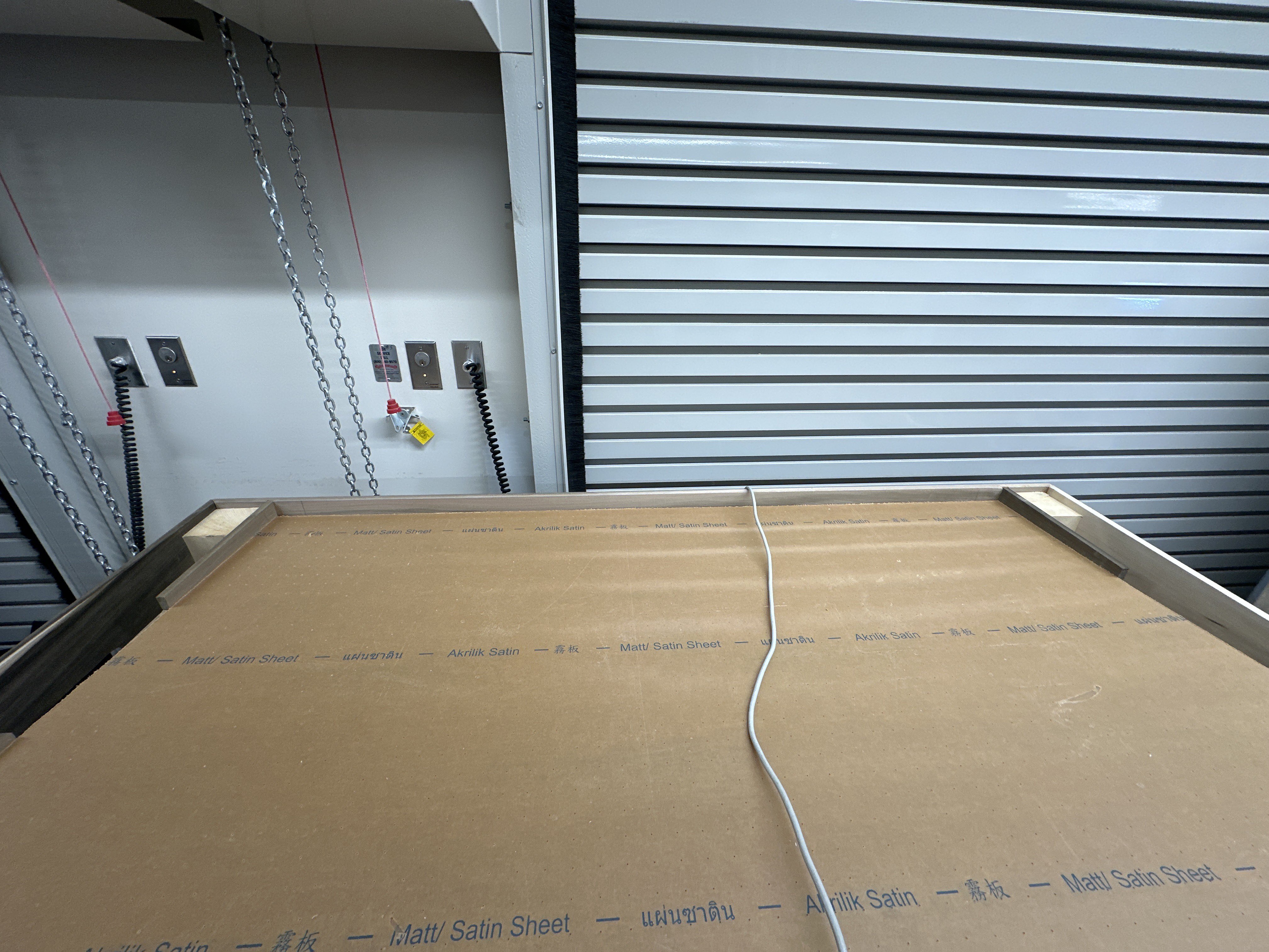
Machining the Acrylic
I made a cam and machined the acrylic at BIDC. Ben and Trevor helped too! Below is a video of the CAM.
This is the acrylic on the table.
Getting Airflow
There was an effort by me and Ben to get airflow on the table working. We got the acrylic to shape.
Next Steps
- Gear up for submission next week
- Building top panels for goal edges
- Finishing all software rough edges
Week 12
Date: 2023-11-10
Week Hours: 7
Total Hours: 140
Description of Project Design Efforts
Due to my attendance at KubeCon NA 2023, I was unable to do much for the project this week. I was only able to help consult the team in the finalization of the construction of the table and a few minor patches (#143).
I do not usually take pictures, but below are some of the pictures I took over the weekend.
I was mostly involved in manning the project booth for in-toto and participating in meetings throughout the rest of the day. I was in Chicago from Sunday through Friday, below is a screenshot of the airbnb I stayed at (Exact address masked to avoid any issues with the platform).
Next Steps
I will consult with the team over the weekend and see what needs to be done to finalize the project and go from there. This coming Saturday I will be going to BIDC to figure out the construction of the acrylic surface. There are also some optimizations I plan to add over the weekend.
Week 11
Date: 2023-11-03
Week Hours: 16
Total Hours: 133
Description of Project Design Efforts
This week consisted of prepping the boards for the table and gluing it together, soldering boards and testing some code on them, and changes to code.
Finishing Boards
I was finally able to finish a bulk of the work, and finished the holes, goal slits, and added cable holes in the table. I used the spindle sander, the router table, the hand router, and the drill press. Below are pictures of the finished boards.
| Smoothened holes | Dados and cable holes |
|---|---|
 | 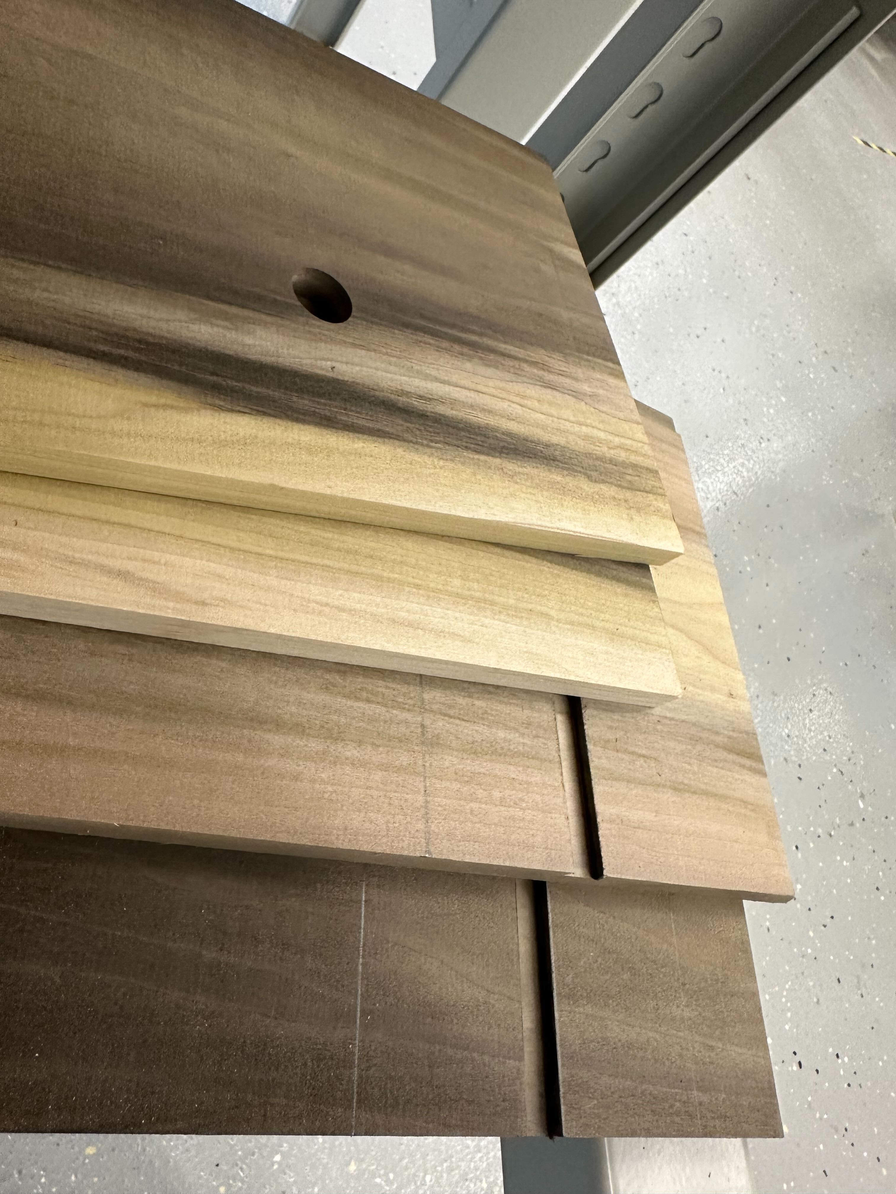 |
Gluing the Table
Me and Trevor glued together the Table together with the boards, below are pictures of the finished products and a video of the process is available in Trevor’s report.
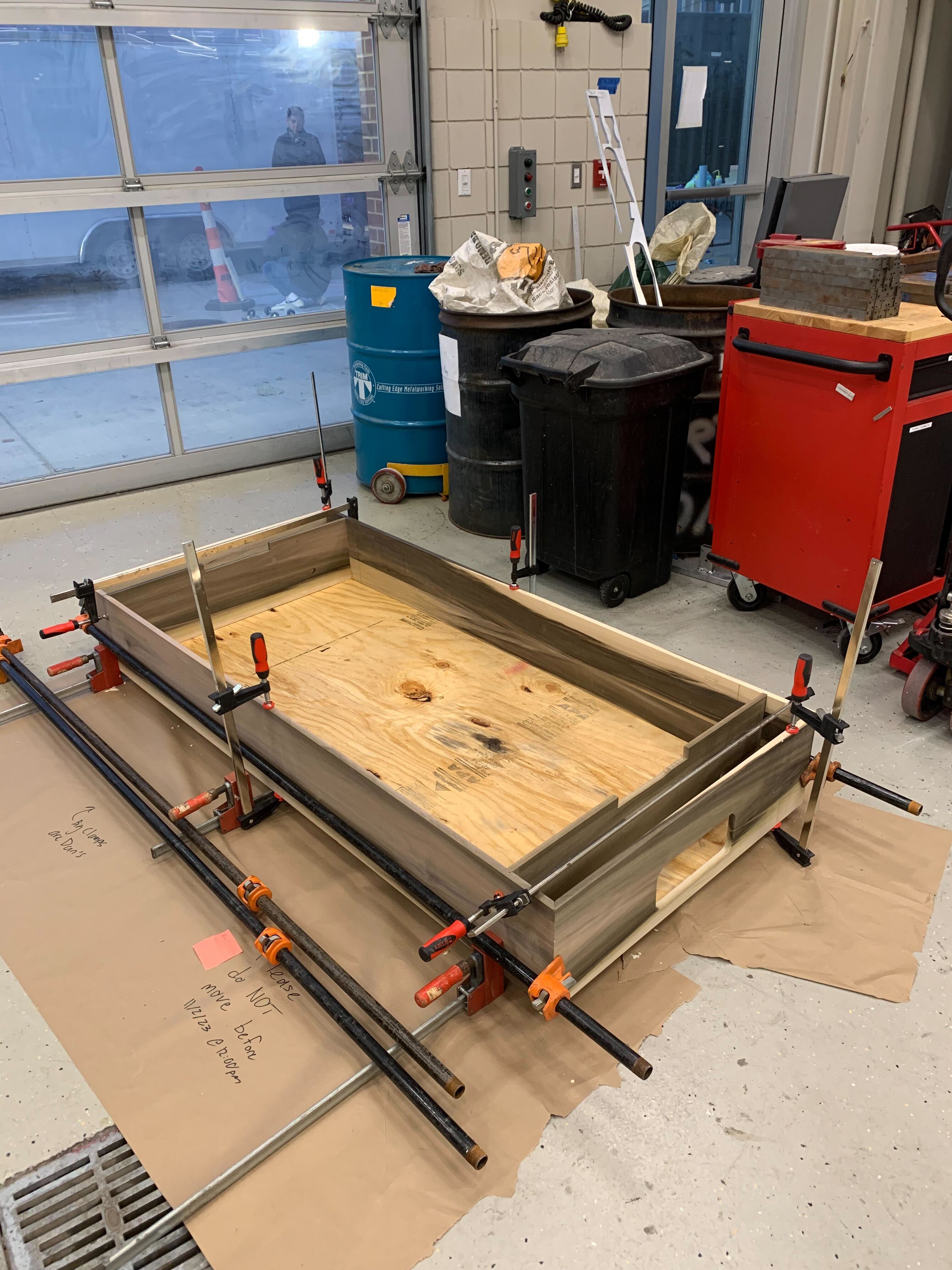 | 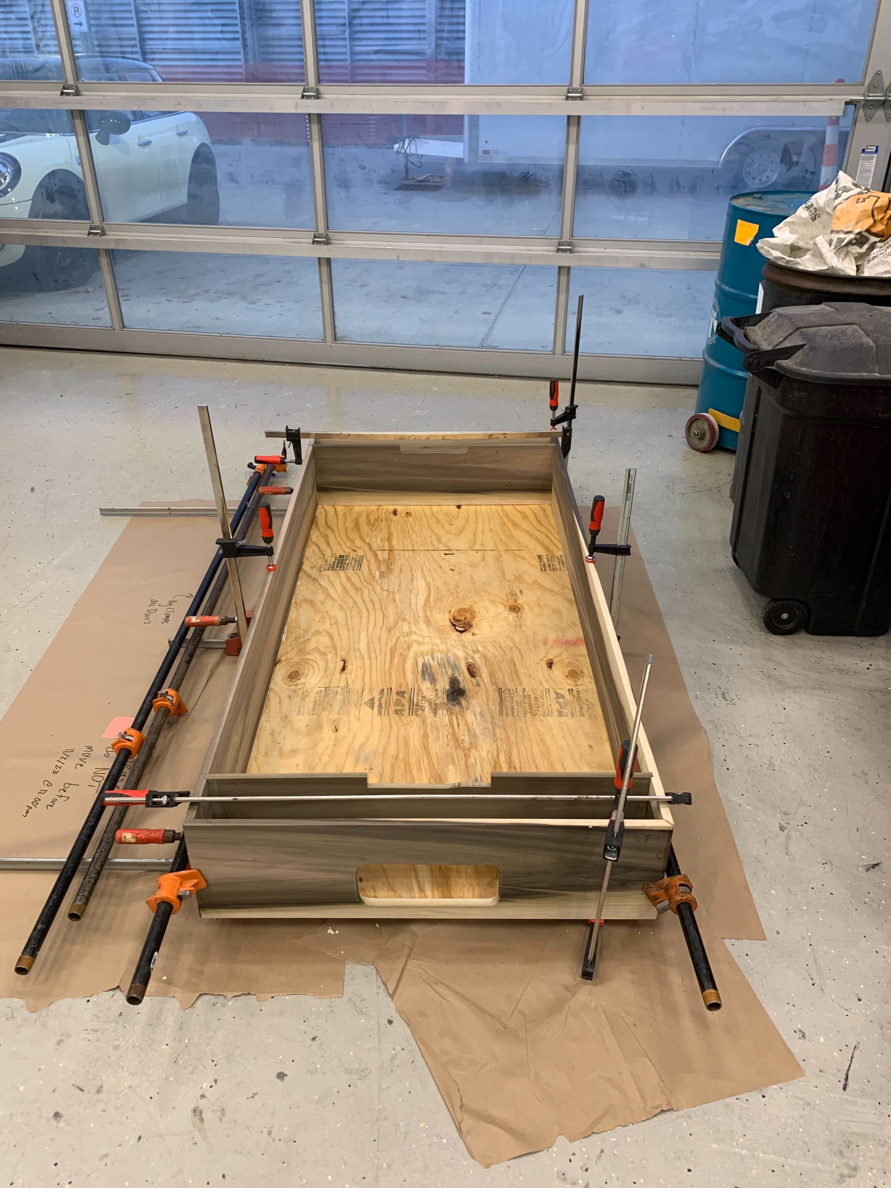 |
|---|---|
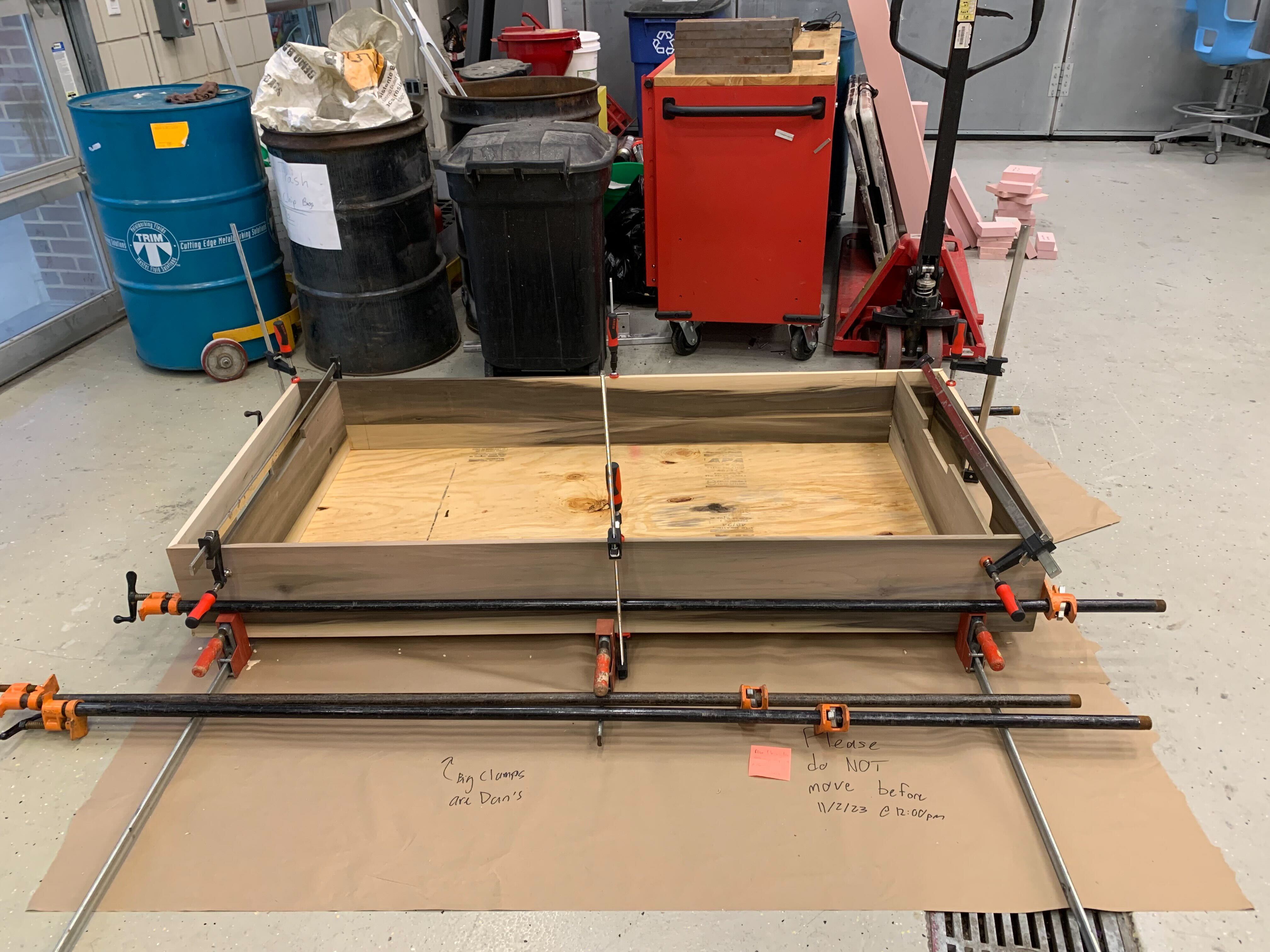 |  |
Soldering Sensor Boards and Doing initial Functionality Tests
I soldered about a third of the pin headers of the sensor boards. Surprisingly enough, it takes longer than expected. Below is a picture of some of the finished boards and them being hooked up to the oscilloscope’s wave gen.
| Before Fix | After Fix |
|---|---|
 | 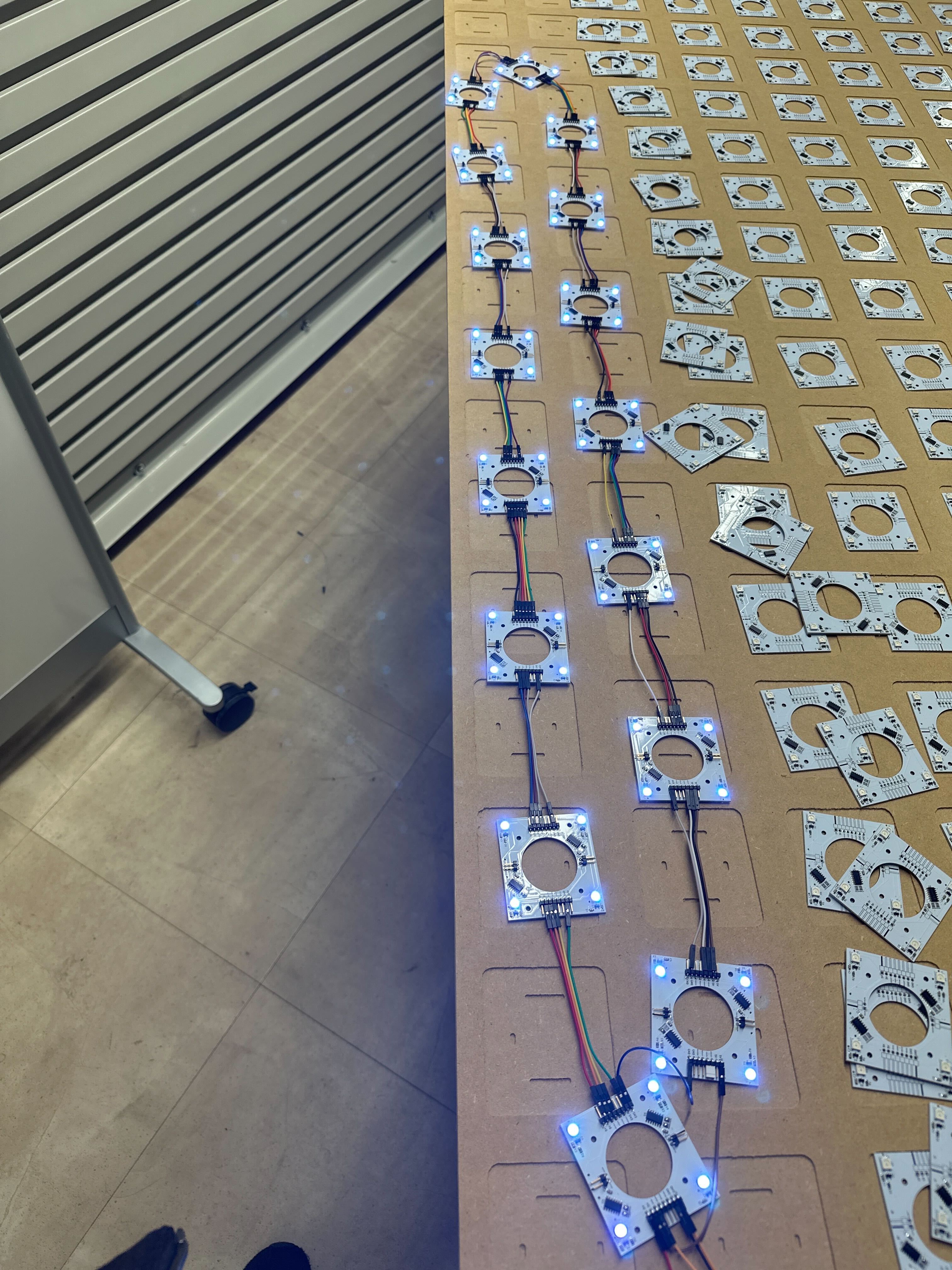 |
As you can faintly tell from the pictures above, the tail end of the boards to the left are warmer and not as bright. After hooking up both GND and 5V to the tail end, the whole line was of the same color. This was because there was a significant voltage drop across a single row. This means that we will need to run wires to both sides of the table to properly power all the LEDs.
Changes to Code
I made various changes to the codebase, below is a list of the PRs:
Next Steps
Since next week I will be at a conference in Chicago, my progress will be limited to things I can do remotely. Therefore, the bulk of my work next week will be optimizing the existing codebase and implementing a lazy algorithm for LED update.
Week 10
Date: 2023-10-27
Week Hours: 14
Total Hours: 117
Description of Project Design Efforts
This week consisted of creating a new CAM for the gantry to run to get the MDF and running it. The secondary efforts surrounded the minor software and firmware optimizations. I also worked on the Legal Analysis (A9) this week, it should be up in Documents.
New MDF CAM and Running the gantry
I noticed that the model I had originally had wrong dimensions and I needed to add tolerances to the outside of the PCB since the gantry cannot make exact 90 degree cuts. Therefore, I made a new model and CAM for it. We decided to cut the MDF down to correct shape first and then just having it be vacuumed onto the table. A TA also changed some parameters and the whole job took much less than one hour, which was more than half than the original job that I was going to run last week. Below is a video of it running in Fusion 360 and below it are pictures of the finished piece.
Minor software updates
I also participated in some software changes, and also have a PR for small optimizations. Here is a link to the PRs: #116, #88.
Next Steps
The goal for next week is to finish some of the exterior of the table. This would not result in the finished table since legs and top covers will still need to be built and designed. I will also begin design and development of an algorithm to store and display animations on the table. This may to wait until all PCBs arrive next week. I will also help soldering the rest of the boards.
Week 8 & 9
Date: 2023-10-20
Week Hours: 20
Total Hours: 103
Description of Project Design Efforts
My work for week 8 was mostly finishing the slides for the presentation and updating the relevant documents and merging pull requests and making minor optimizations. As for week 9, I worked with Will with the encoder, fixed a few branches for merging in git, and worked on the table.
Presentation Prep
In Documents, you can view the presentation slides the whole team worked on. I also updated A2 and A3.
Working on the Encoder driver
I worked with Will to get some of the delta logic working, PRs are available here and here. One of the main concerns was figuring out when and where we wanted it to update using the encoder scaling factor.
Fixing git branching
I spent a good amount of time fixing and cleaning up a few of the branches in the repository.
Working on the Table
For the presentation, I made a whole model from scratch since a lot of the measurements have changed. Below is a picture of it.
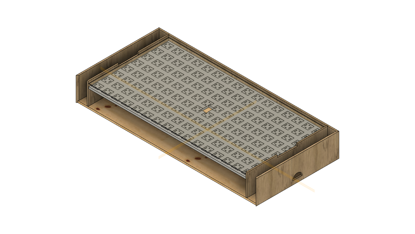
After, I made a CAM for the MDF so our PCBs can properly fit on them. However, we had to push running the gantry back since we weren’t sure whether or not having the PCBs assembled will change the dimensions of the final PCB. Below is a video of the simulation of the CAM.
Since I couldn’t run the gantry, I used the panel saw and table saw to cut the plywood to the final dimension of 71.25" x 32.5 and also cut down the MDF to a smaller size of 70" x 40" to make carrying it much, much easier.
Later, I also cut up the holes to grab the puck using the drill press and a cordless jigsaw. This was followed by adding rabbets joints to the outside edges. Below are pictures of the result.
| Almost finished short edges | Almost finished long edges |
|---|---|
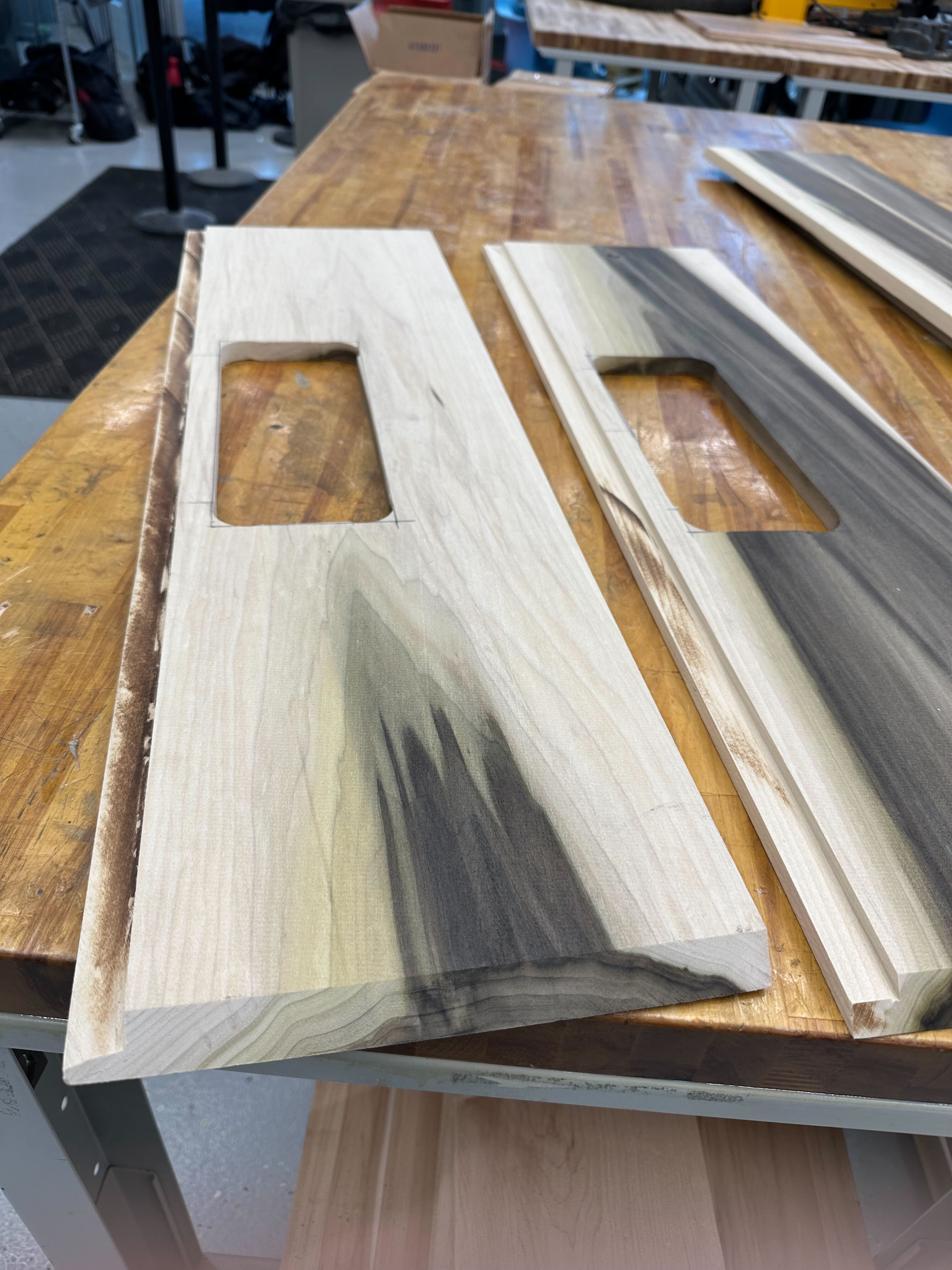 |  |
Next Steps
If all goes well, the table exterior and MDF will be finished next week, unfortunately, the CAM will have to be redone since I cut down the MDF. I will use the spindle sander to clean up the big holes and will need to add holes and dados to a few panels before gluing it all together. Finishing the MDF will give us more space to put all the sensor PCBs for testing. I will also begin helping the team design and build an algorithm to test integration between sensors and LEDs.
Week 7
Date: 2023-10-06
Week Hours: 18
Total Hours: 83
Description of Project Design Efforts
This week, we were able to finish most of the sides of the table. The next steps are to make the dados and holes for the table itself. I also solder together a bunch of the daughter boards and test them.
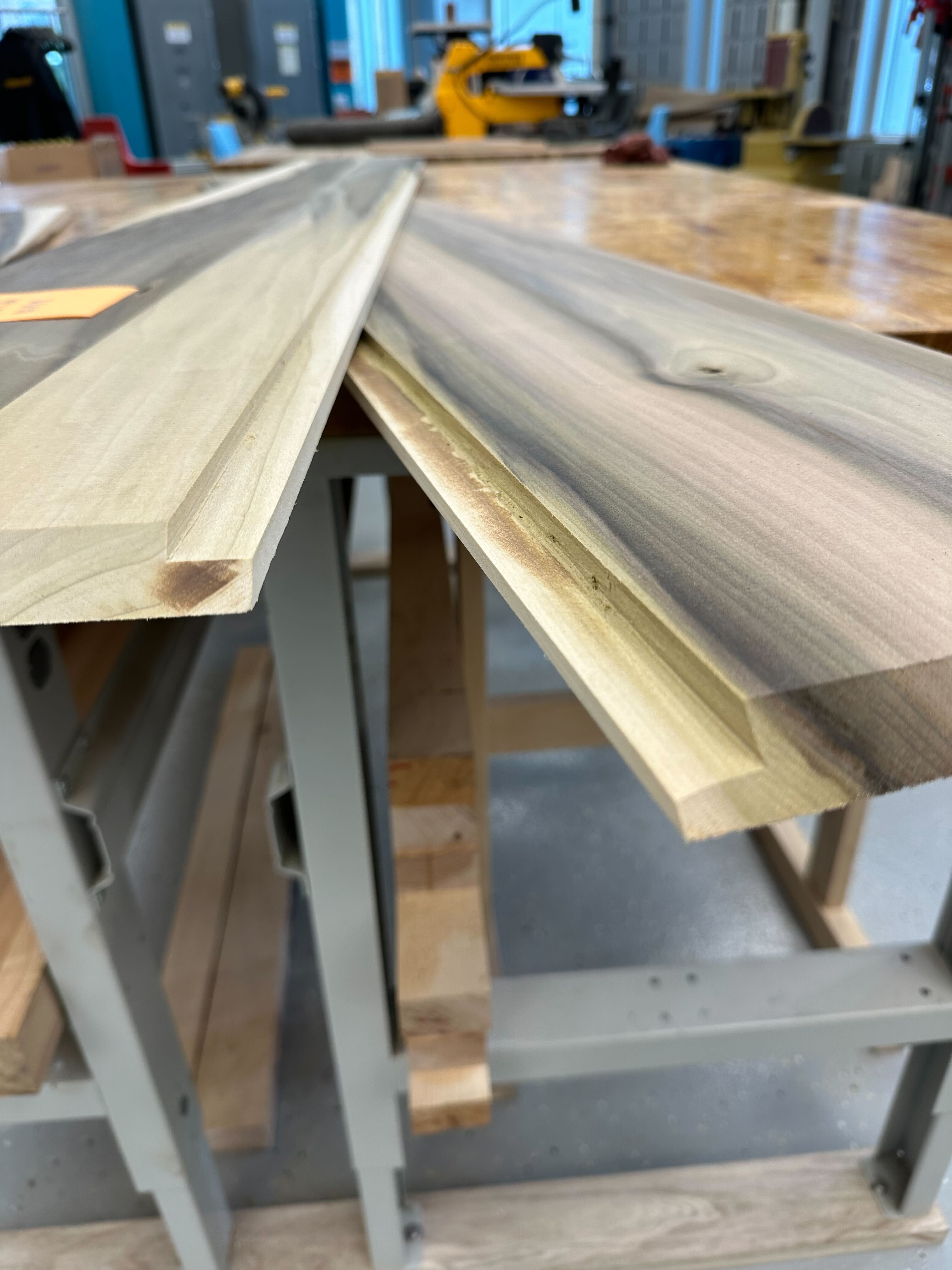
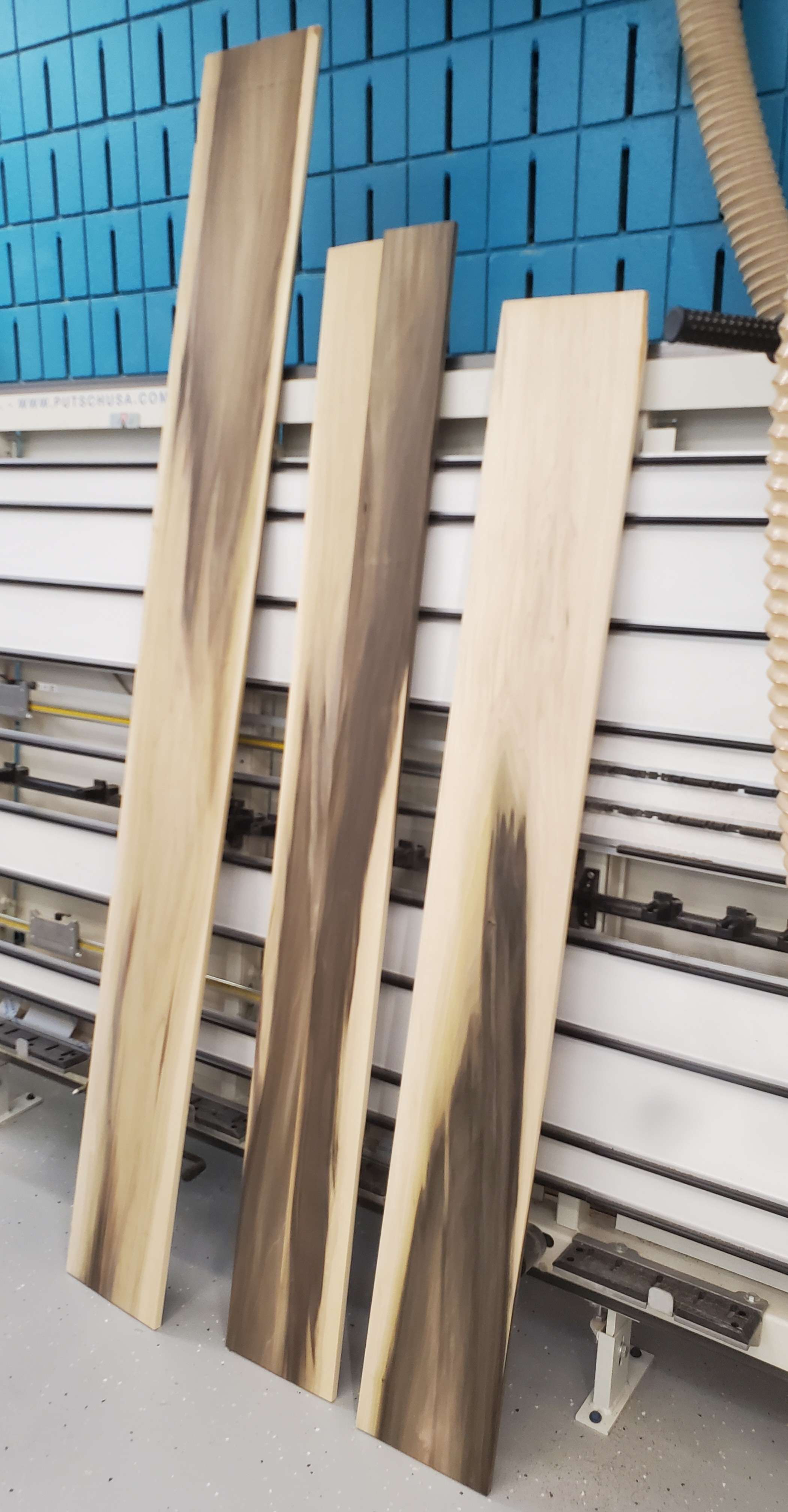
Finishing the sides of the table
Me and will finished the sides of the table, finalizing the overall dimensions of the sides of the table.
Below is a picture of some of the finished sides.
For the two outer edges, we added 45 degree miter cuts and below are the dimensions of each edge:
Outside Long Edge:
  - Width: 9 1/2"
  - Length: 72"
  - Thickness: 5/8"

Outside Short Edge:
  - Width: 9 1/2"
  - Length: 33 1/4"
  - Thickness: 5/8"

Inner Short Edge:
  - Width: 8 3/4"
  - Length: 32 3/8"
  - Thickness: 1/2"
For the dados, the inner short edge will slide into a 3/16” dado in the outside long edge. There will be 1/4” dado in the bottom of the outside edges that will sit with the base.
To finish the final edges we had to use the planar and jointer to obtain a flat plank of the correct thickness, and we then used the table saw and Miter saw to cut it to width and length. The table saw was then used to get the 45 degree miter edges.
We were unable to cut out the dados as Dan, basically the head of the wood shop at BIDC, was not in office. This is because we would have needed to change out the blade on the table saw.
Soldering the boards and putting together electrical components
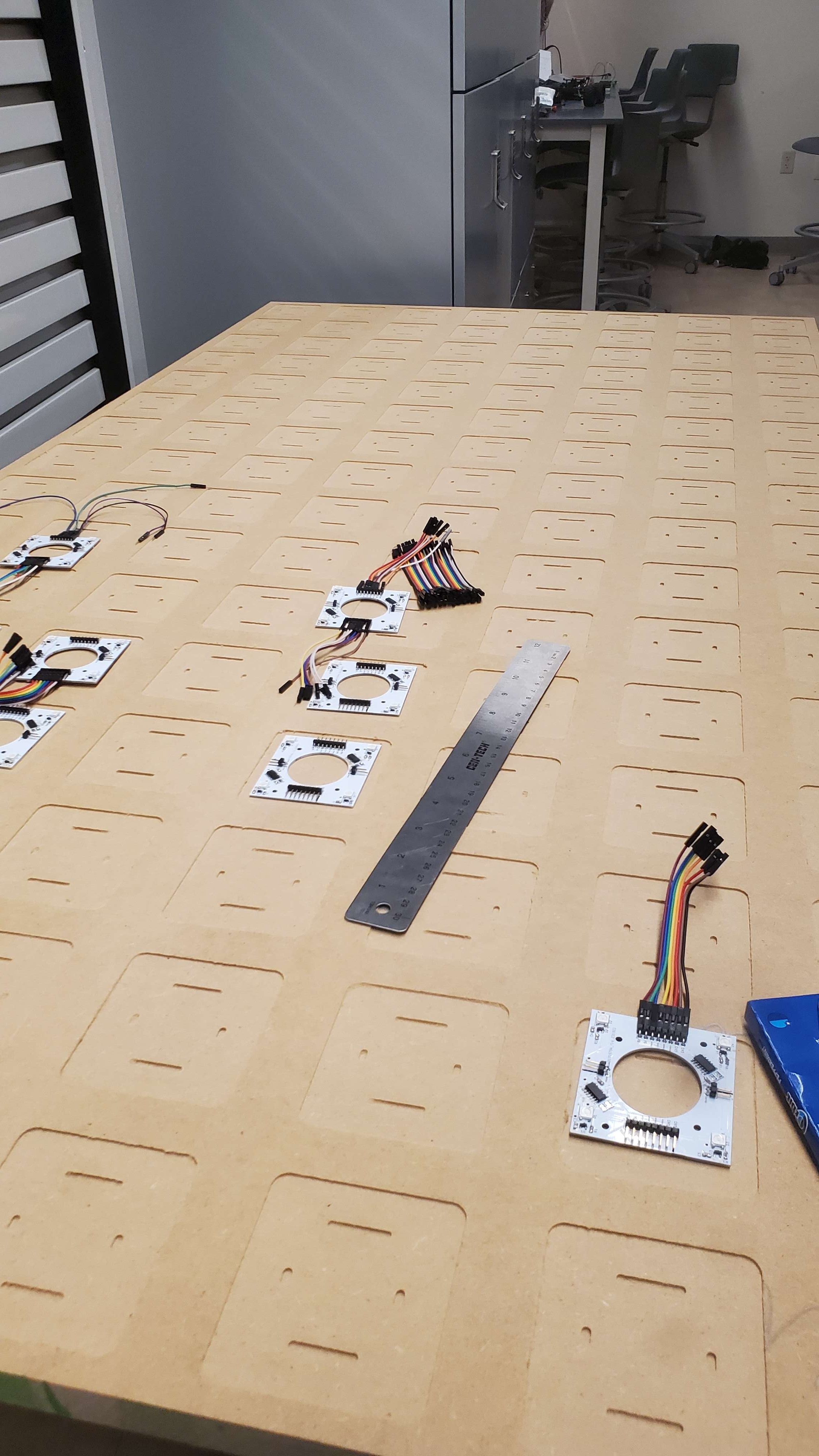
Since the parts from Digikey have finally arrived, I soldered a few sensor boards so that we can do some preliminary testing.
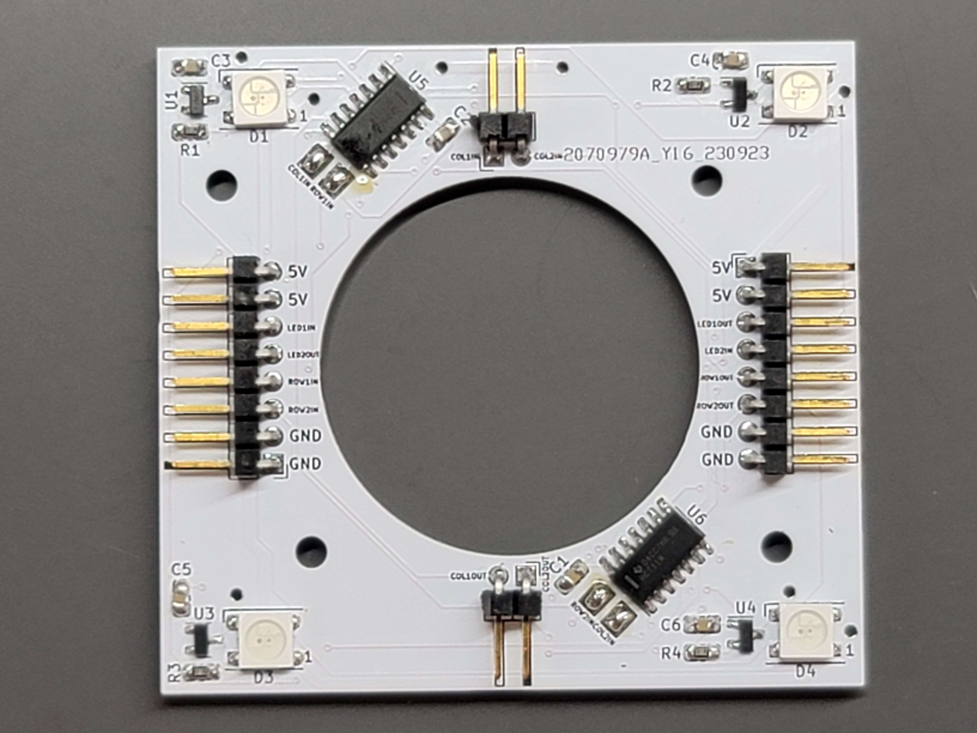
Below is a picture of a finished soldered board:
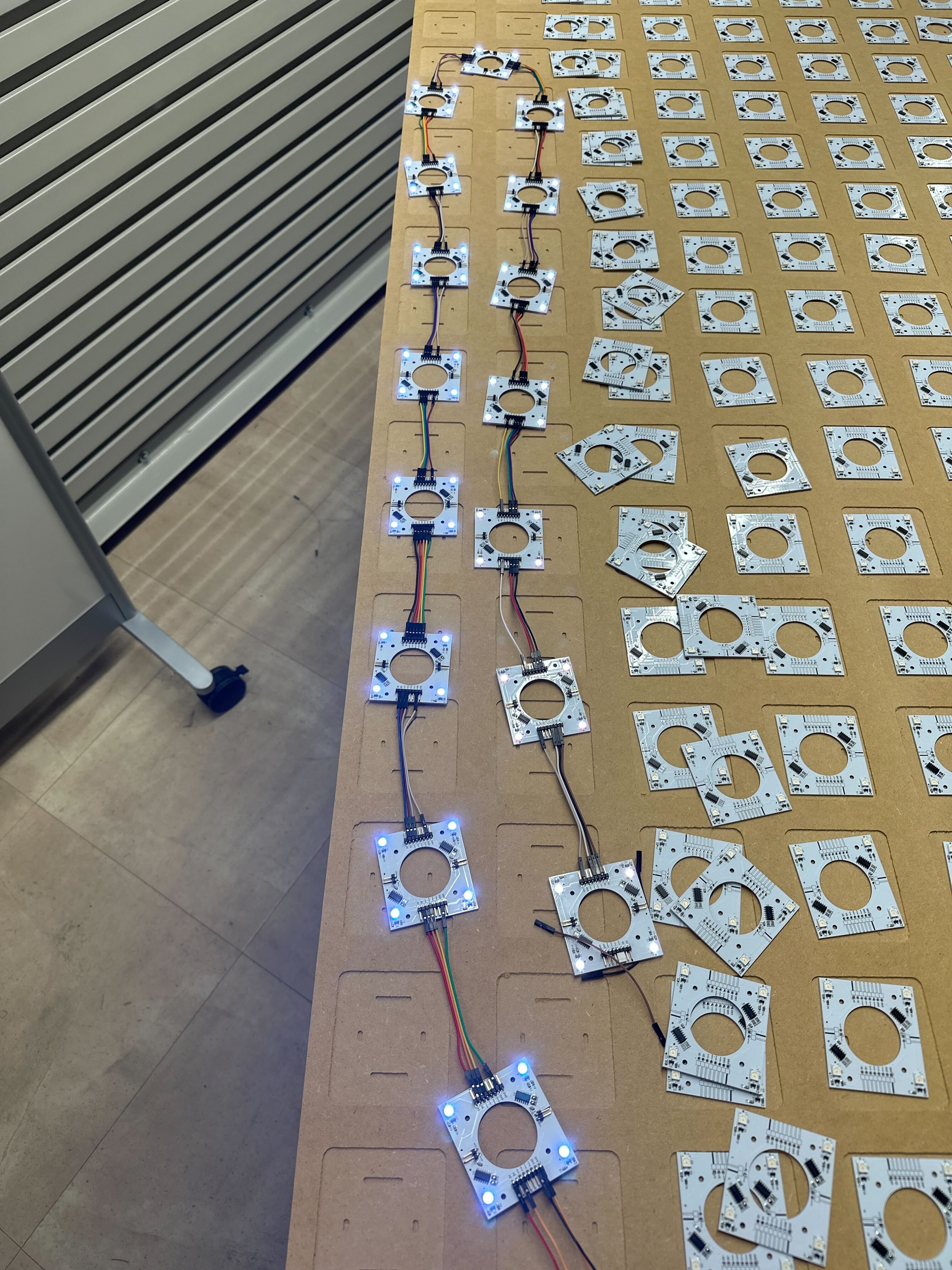
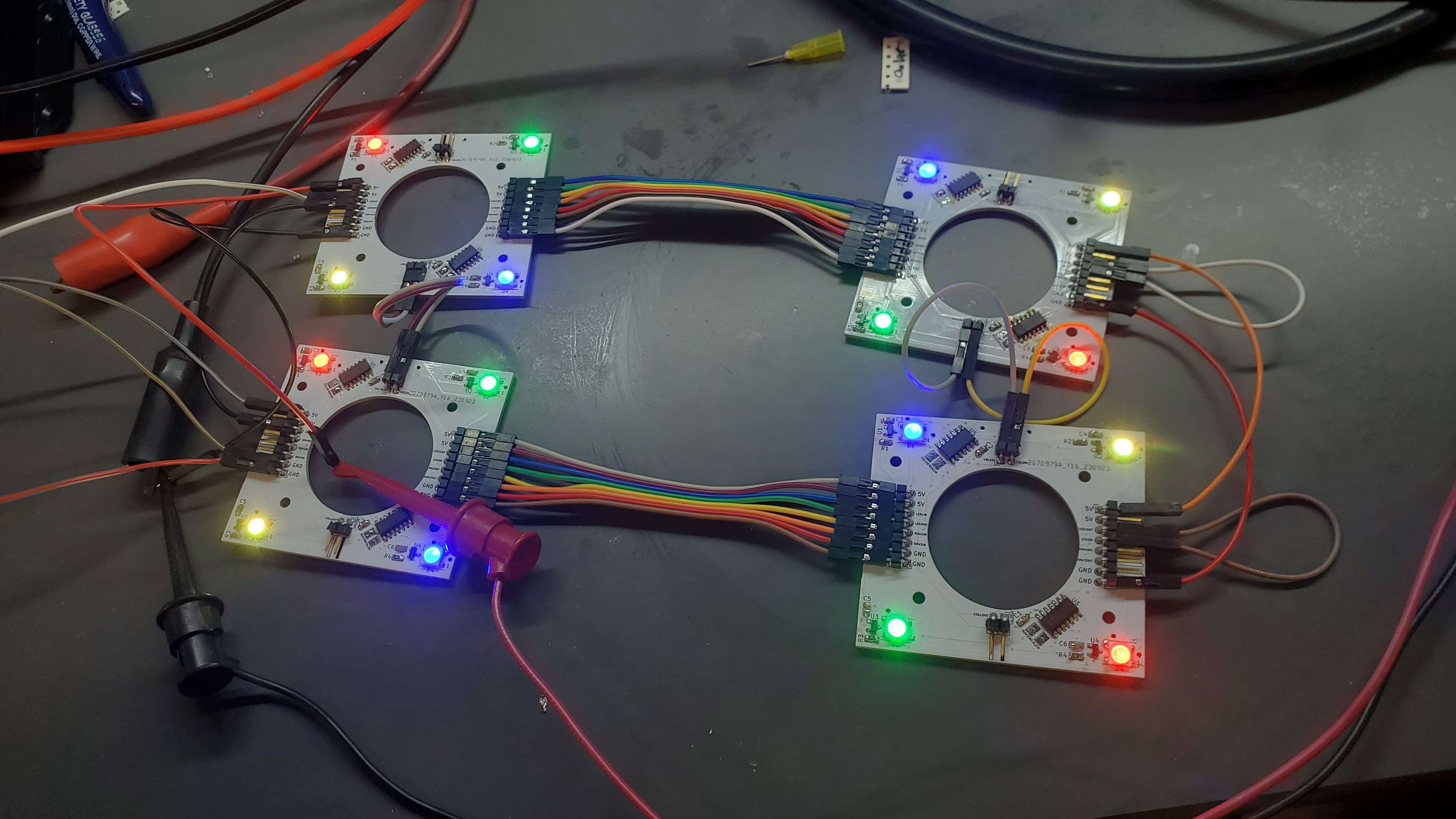
And below is a picture of a bunch of them connected together with Will’s code:
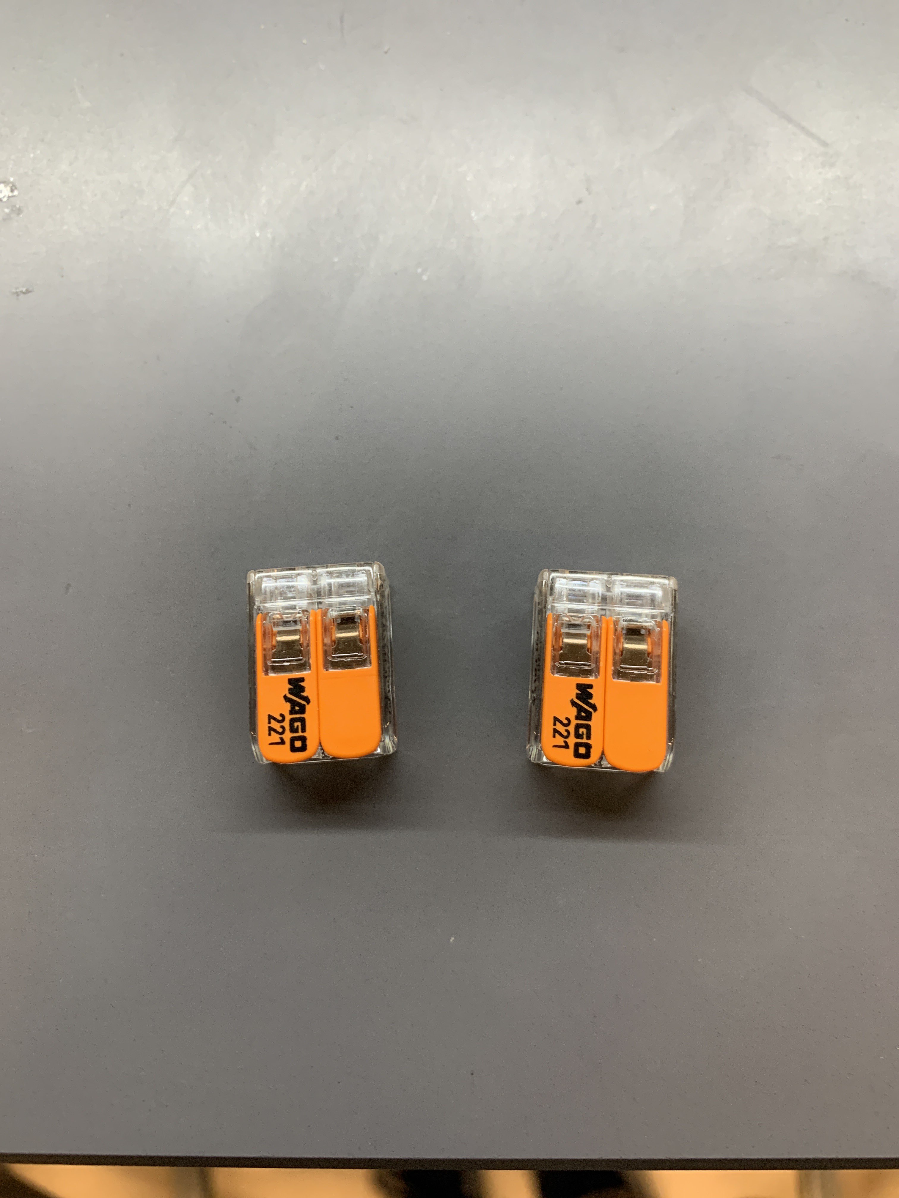
We also got the following connectors to connect the blower with a three-prong
AC wire for power instead of the somewhat sketch method we had previously:
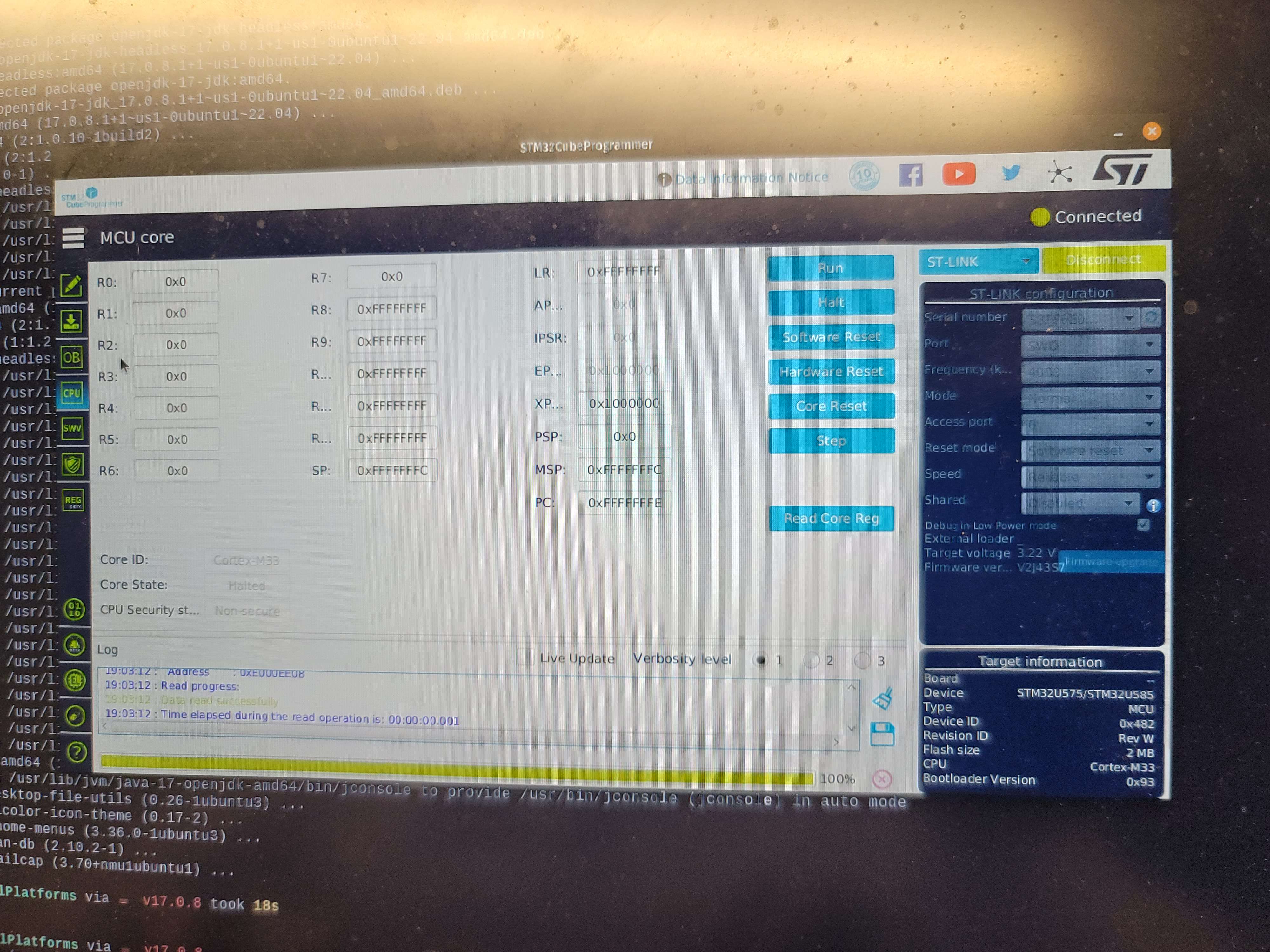
After Ben soldered the STM32 U585 on the first revision of our master PCB, I was
able to detect the chip and get its register values with STMCubeProgrammer.
Testing the soldered boards
From the picture above, you can see that we are now testing how we are connecting our daughter boards. We are able to individually connect the LEDs and were able to see the hall effect sensors on the oscilloscope. We plan to set up a proper testing rig since for the hall effect sensors since we could not put it all together properly. A video was not taken but it was shown in ManLab.
Fixing documents and preparing for midterm review presentation.
We began updating and fixing some of the documents so that we can put it all up on the website before the midterm review presentation.
I set up the slides and we began working on them. The slide deck will be up in Documents by Wednesday.
Next Steps
Besides working on the slide deck for the presentation and updating all technical reports. I will be working on the CAD model of the table so that it can be worked on in the wood gantry. I will also help with setting up the architecture of the firmware.
Week 6
Date: 2023-09-29
Week Hours: 12
Total Hours: 67
Description of Project Design Efforts
Building the Table
This week, a significant portion of my effort was dedicated to the construction of the air hockey table at the Bechtel Innovation Design Center (BIDC). Here are the key activities and developments related to this:
-
Material Sourcing: I successfully sourced the materials needed for the table from different locations:
- From Home Depot, I acquired a sheet of plywood, MDF (Medium-Density Fiberboard), and frosted acrylic, which will be integral to the construction.
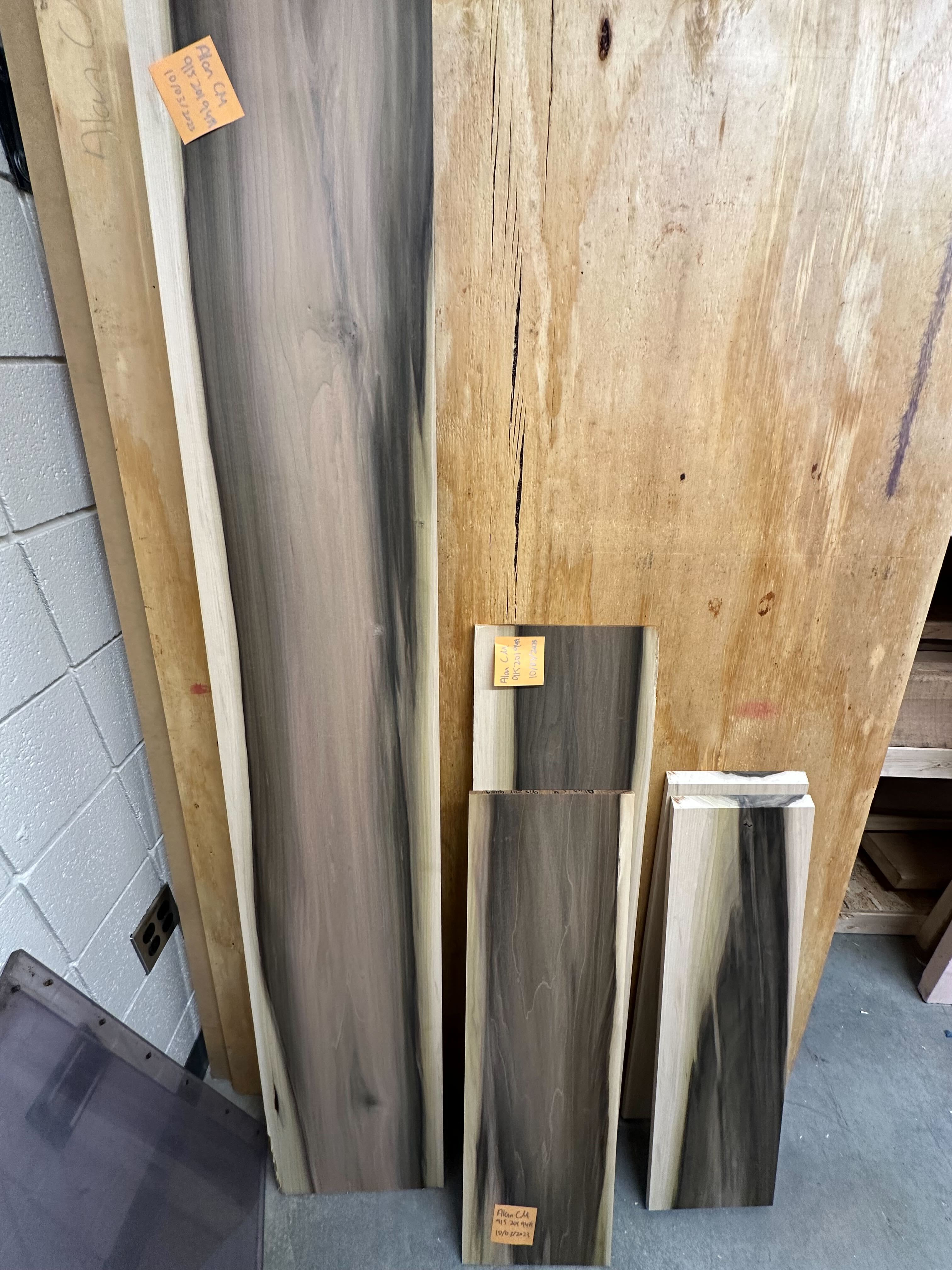
- Additionally, I obtained materials from the BIDC stock room, specifically poplar hardwood, which was chosen for its cost-effectiveness and availability of flat 1” planks suitable for the project.
-
Table Construction at BIDC: I initiated the construction of the air hockey table at BIDC, working diligently to transform these materials into the desired structure. Some of the key activities include:
- Conducting consultations with BIDC Teaching Assistants (TAs) to gather insights and recommendations, which informed several design changes.
- Opting for poplar hardwood as the primary material for the project, considering the availability of suitable planks and their cheaper cost. The TAs would not have liked it if my team were to use up a lot of expensive wood for the project.
- Utilizing woodworking tools such as the jointer, planar, bandsaw, and tablesaw to shape the sides and create planks for the table structure.
Below are some images from the progress:
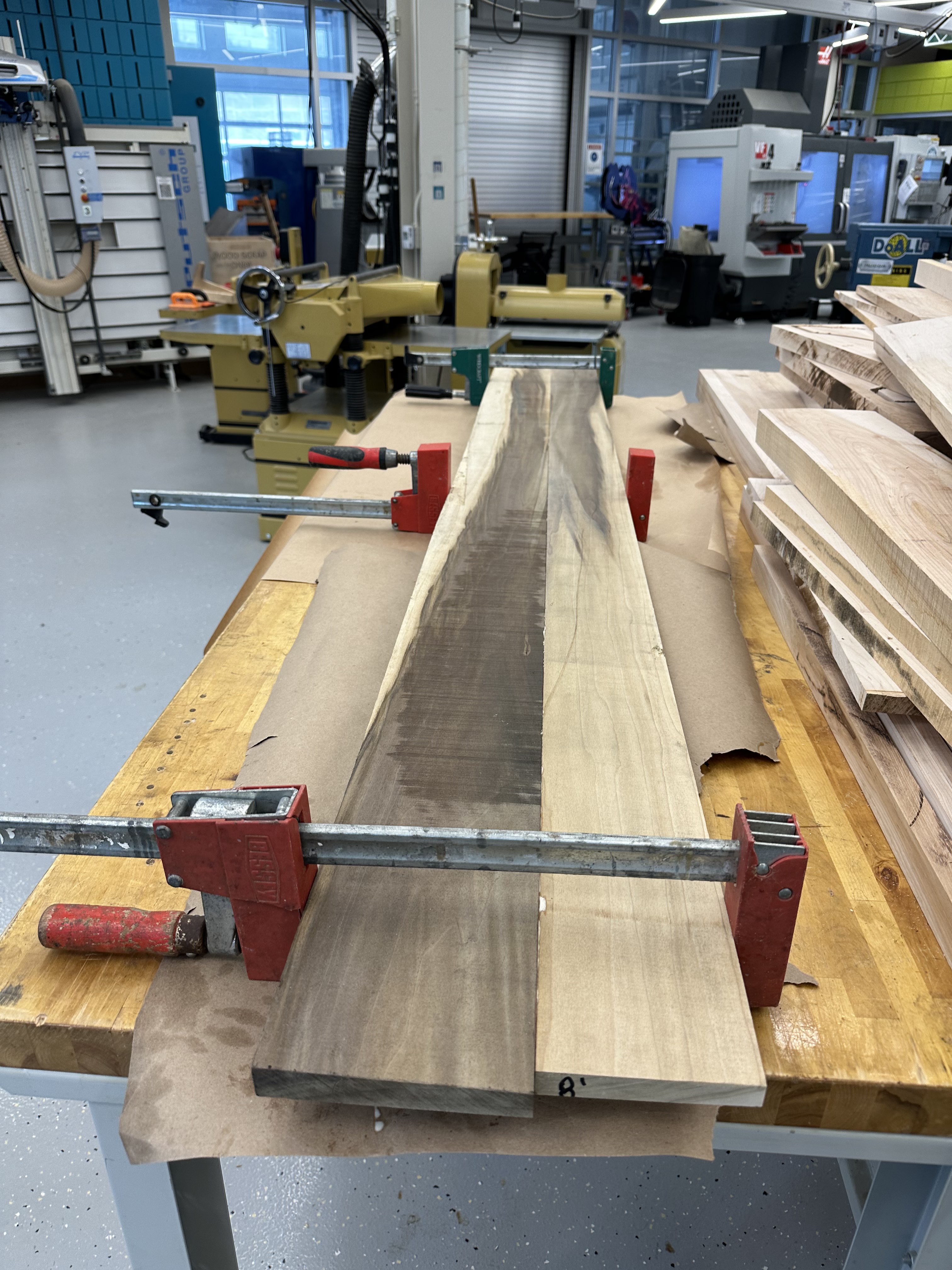 | 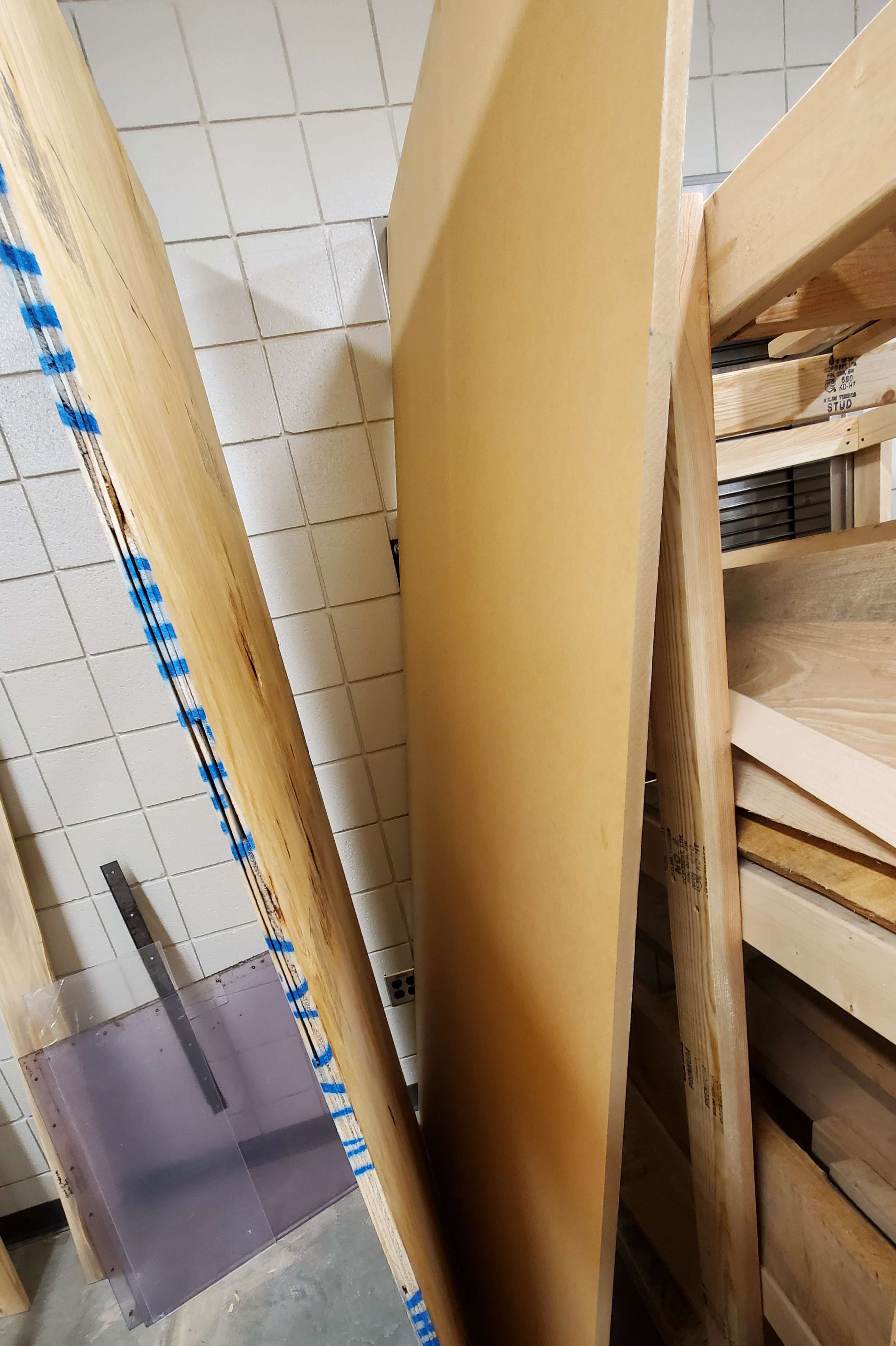 |
|---|---|
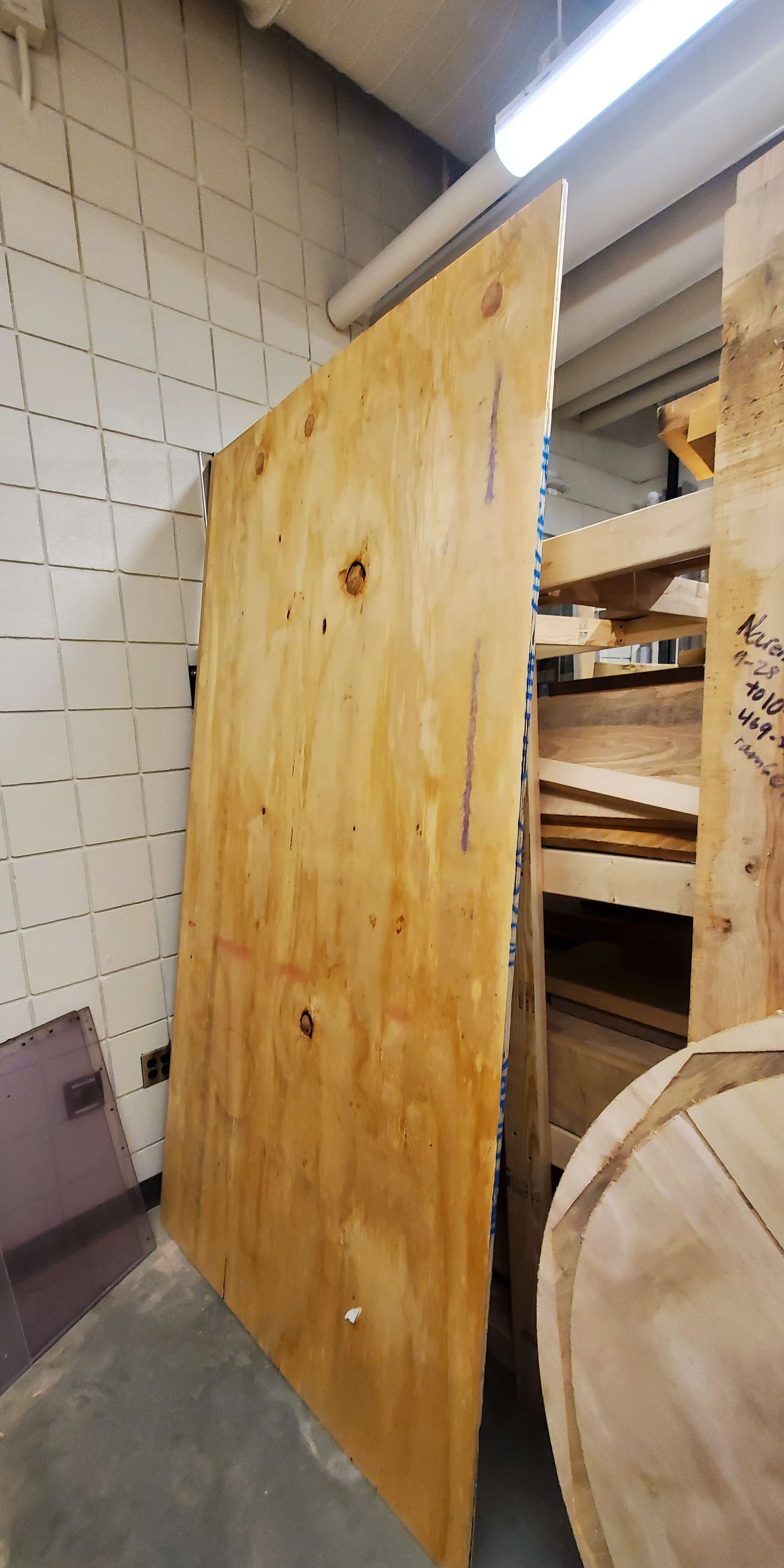 |  |
Testing of Large Electrical Components
Another significant aspect of this week’s progress was the testing of large electrical components essential to the project’s functionality. Key highlights of this testing phase include:
-
Air Blower Testing: We received various electrical components this week, including an air blower. I actively participated in the testing of the air blower to ensure its proper functionality within our setup.
-
Power Switch and Supply Testing: Additionally, I was involved in testing a controllable power switch and the power supply units required for our microcontrollers. Ensuring these components work as intended is critical to the overall project.
Next Steps
As we move forward, the following are the key tasks and priorities that lie ahead:
-
Continued Table Construction: My immediate focus will be on progressing with the construction of the air hockey table at BIDC. I will continue to follow the guidance and recommendations of BIDC TAs to ensure the table’s successful completion. Some changes would also need to be made as some dimensions have changed.
-
Soldering PCBs: I will actively contribute to the soldering process of PCBs, a crucial step in the project’s hardware development. This collaborative effort will play a significant role in bringing our project closer to realization.
Week 5
Date: 2023-09-22
Week Hours: 11
Total Hours: 55
Description of Project Design Efforts
This week’s focus was mainly on designing the table and getting inforation from BIDC, updataing the team’s webpage, the BOM, and the tools used to develop on the STM.
Designing Table in BIDC
This was the bulk of my responsibility this week. I began the process of creating a project in the Bechtel Innovation Design Center (BIDC). I consulted with Teaching Assistants (TAs) from the Woodworking station on most of the materials we will be using, as well as the overall design of the project.
Below are the notes I had from my initial meeting.
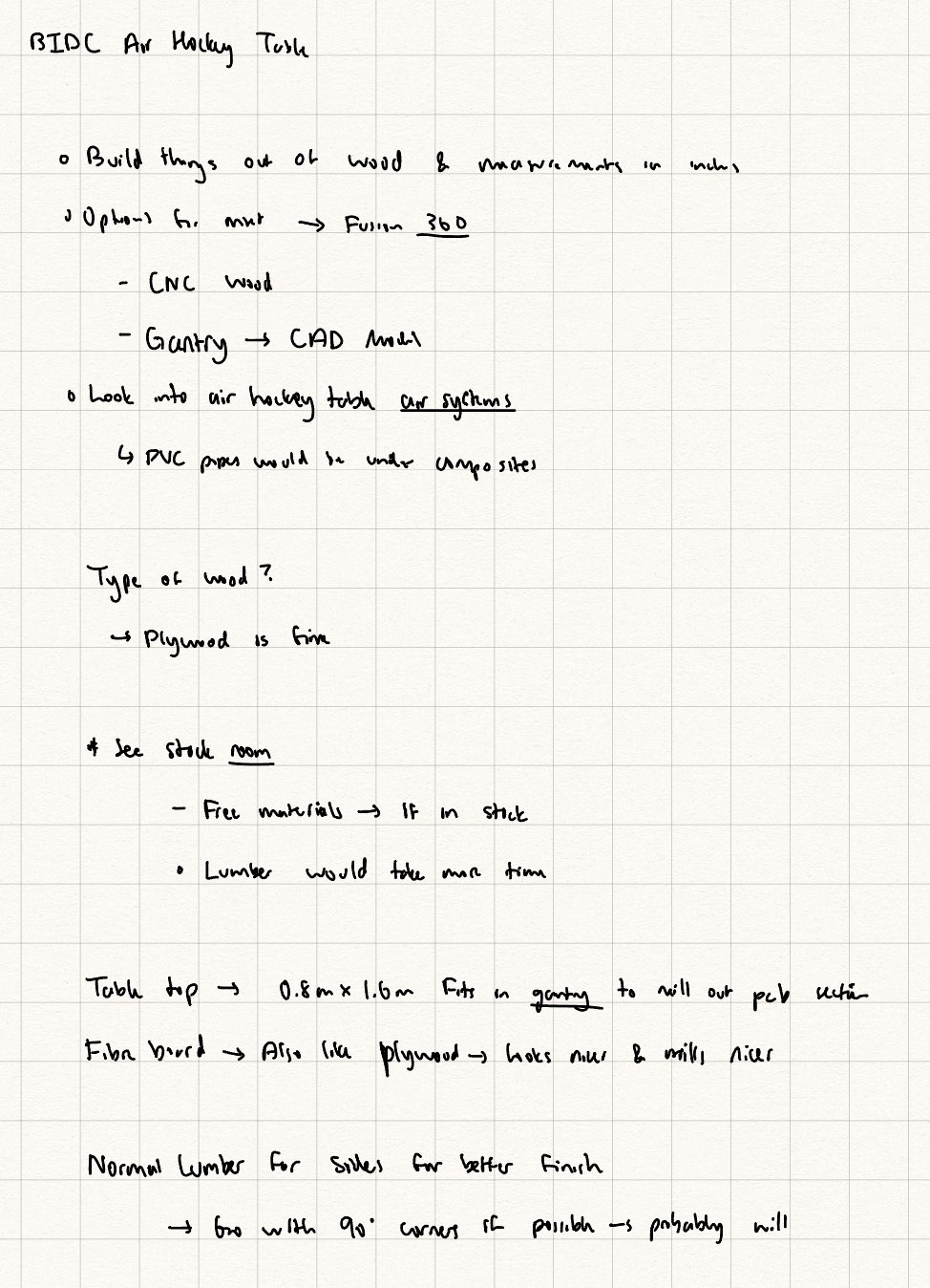 Caption: Notes from the first BIDC Meeting.
Below are the sketches I created after the initial meeting and a second consultation with the TAs.
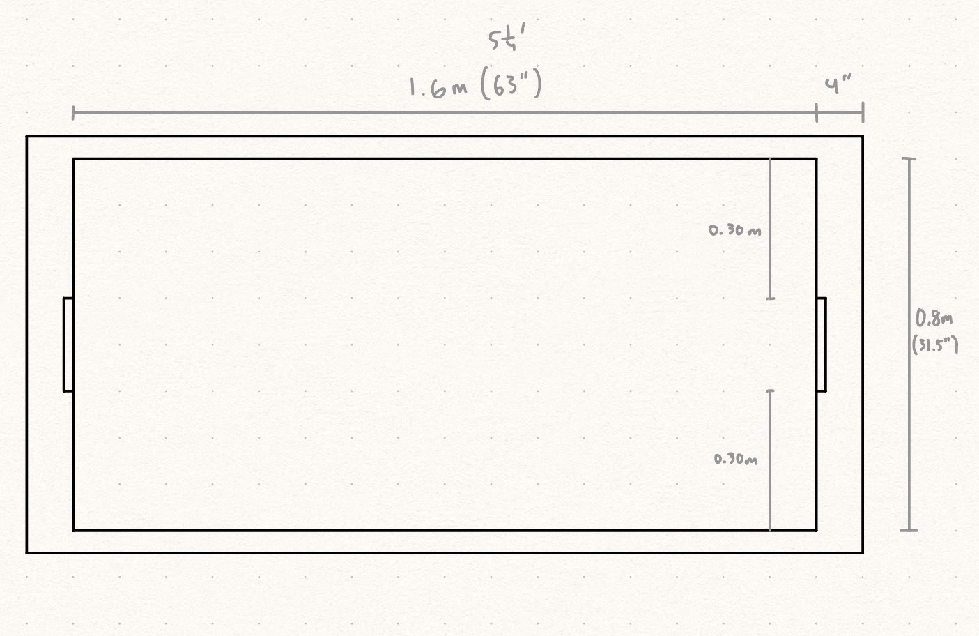 Caption: Sketch of the top view of the table.
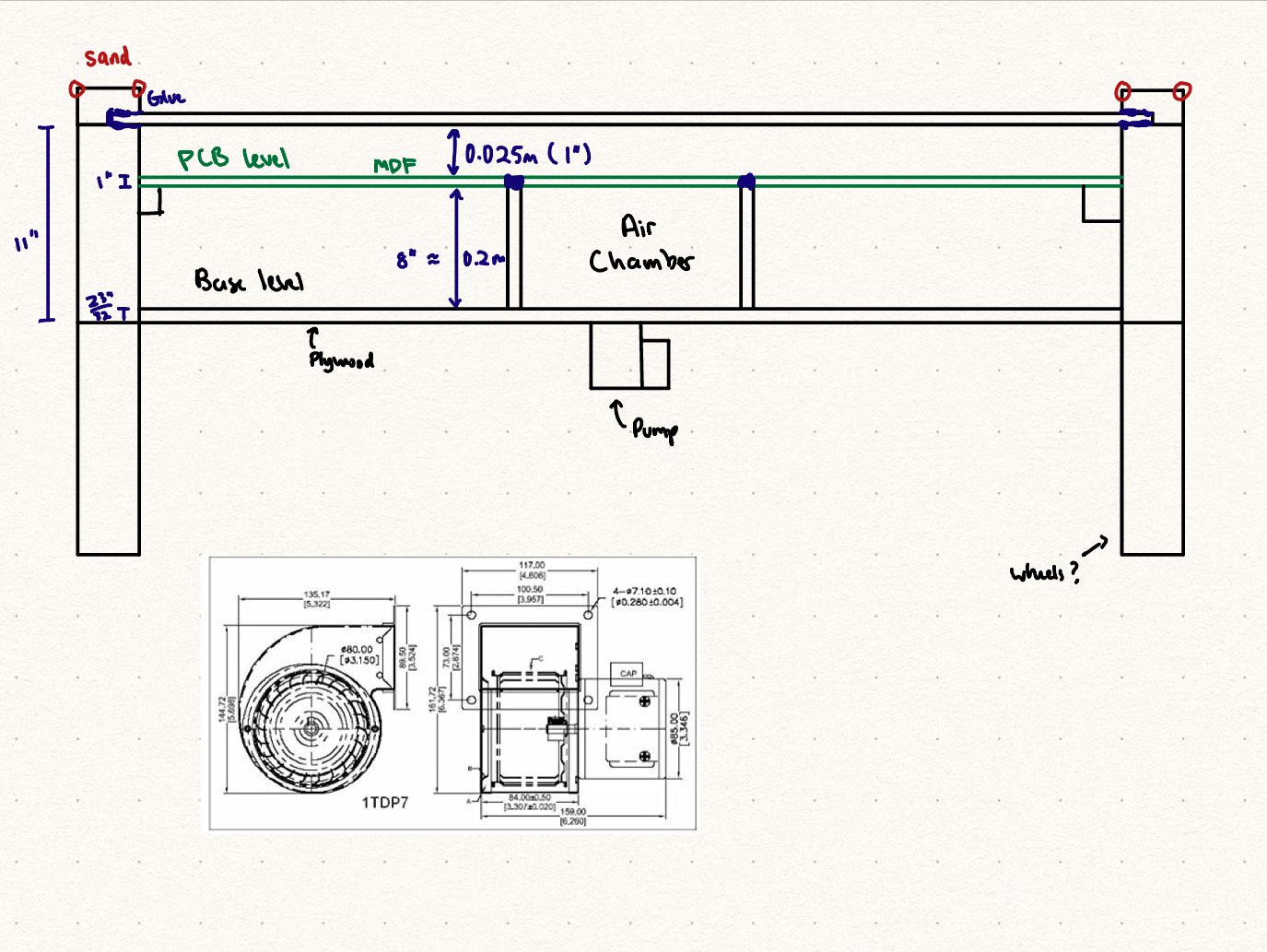 Caption: Sketch of the sid view of the table.
 Caption: Sketch of the front view of the table.
A few of the considerations have been made:
- The middle layer should be made of MDF since it would be easy to machine and which will allow us to machine out insets for the PCBs to go into and we could cleanly machne out the holes.
- An intermediary air chamber will be used to spread out the “air” of the pump.
- Since we would ideally not have any of the center PCBs removed, we will attempt to replicate the same effects by having the air chamber spread out the air over smaller holes in the MDF layer
- The acrylic top will be thin, therefore there will be stands between the MDF layer and the acrylic to keep it solid.
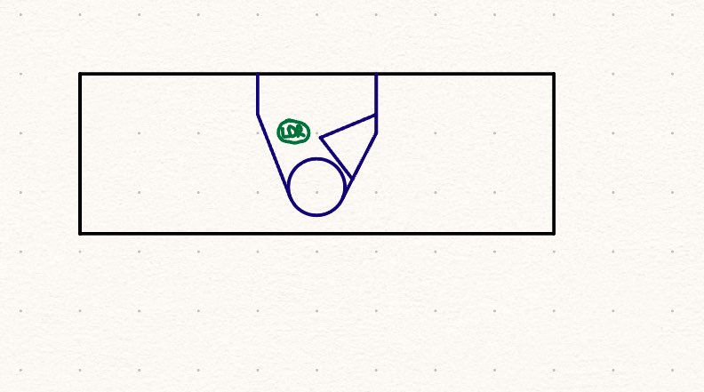
- The puck goal feeder will channel the puck to a narrow entry, replicating the method from this video.
The goal is to obtain the materials over the weekend and start booking equipment time and build the table over the span of Week 6 and 7.
Updating the Project Homepage
I updated the project description and PSDRs provided the feedback from the teaching staff during ManLab. A link to the corresponding PR is here.
Project Bill of Materials
I helped update some of the items in the Bill of Materials as the team was working on filling out the purchase request. It is still rudamentary but it should be up in Documents by end of Saturday.
Getting STM32 VSCode Extension Working
I spend a significant amount attempting to get the STM32 VSCode extension working. However, major functionality such as flashing the STM and debugging would have required a significant amount of setup with CMake and gdb. Therefore, I decided to stop working on it after about ~5 hours of trying to get it working. The CMake set up needed manual changes and there was a lot of features that were missing.
After getting Cube IDE working on my machine, I opened a PR to have the directory naming be consistent across the project, PR linked here. I figure this was because Windows is not case sensitive.
Next Steps
The next steps I have planned are to source the materials for the table and build it in BIDC. I will probably consult a TA again to figure out the best way to go about building it, but I am confident I can get it done by end of week 7.
Another thing I will be focusing on is work on the components of the firmware that are not worked on at the moment. This will be determined at a later time asynchronously. I will probably try to build on a breadboard a simulated daughterboard that way the rest of the guys can work on a prototype of what the board will act like.
Week 4
Date: 2023-09-15
Week Hours: 16
Total Hours: 44
Description of Project Design Efforts
I did not have as much time to work on the project since I attended IR and other adjacent career fairs. However, I was able to work on a wide variety of things for the team.
Setting up Githup Projects for Task Management
The team faced challenges in monitoring all the tasks effectively. To streamline this, I suggested the use of a kanban board, enabling us to view and manage the team’s tasks in a consolidated space. I utilized GitHub’s built-in Projects feature and linked our repository to a new project. You can access the GitHub project here. Additionally, I’ve provided a screenshot of the board below for a quick overview.
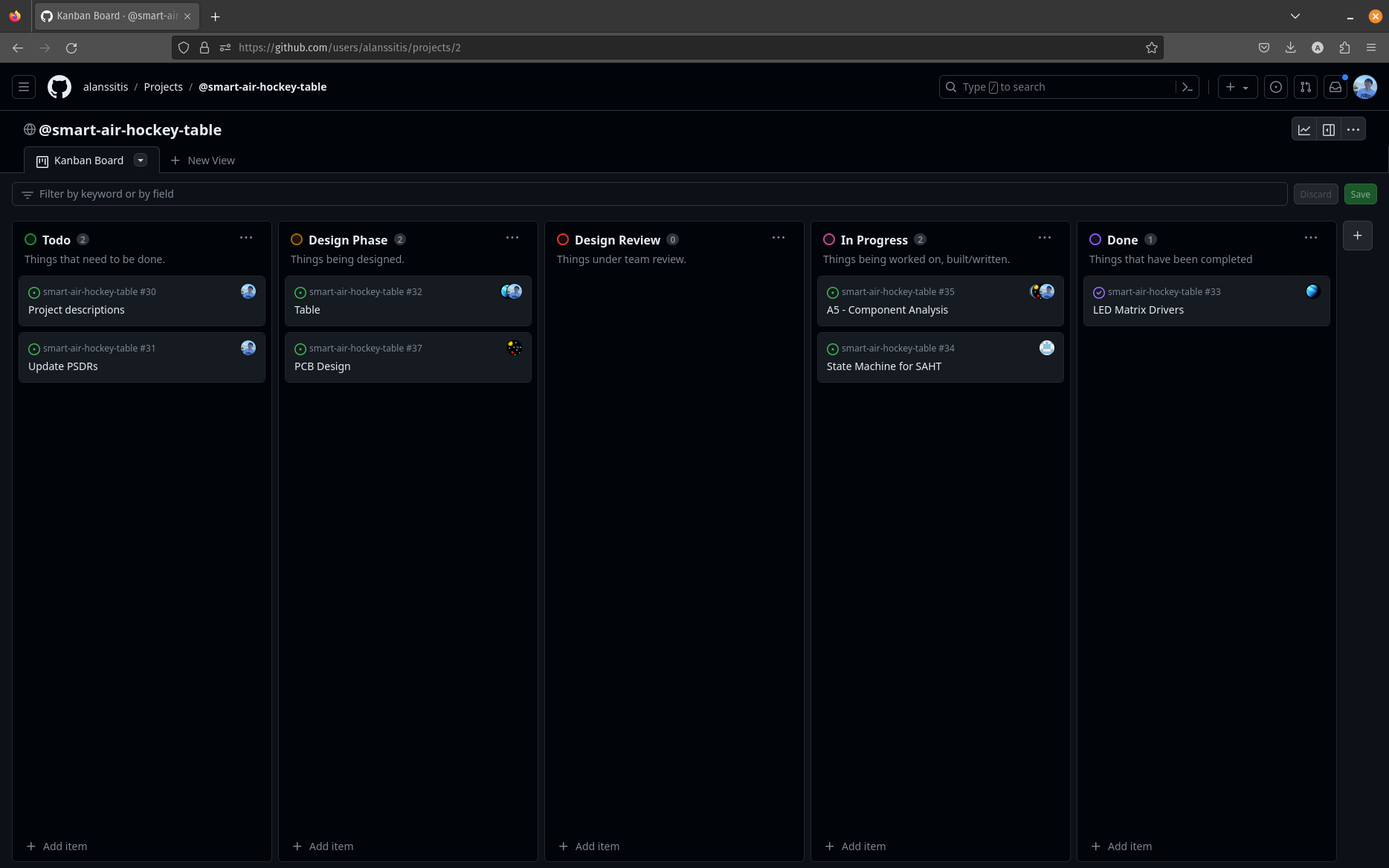 Caption: Screenshot of the GitHub project page
Finalizing the System Flowchart
I worked with the rest of the team to make the project’s flowchart. Below is a cleaned up diagram of it. It was adapted from the diagram drawn from the Software Overview. One of the major changes that whoever got scored on will have the puck, instead of needing to place the puck in the middle of the playing field.
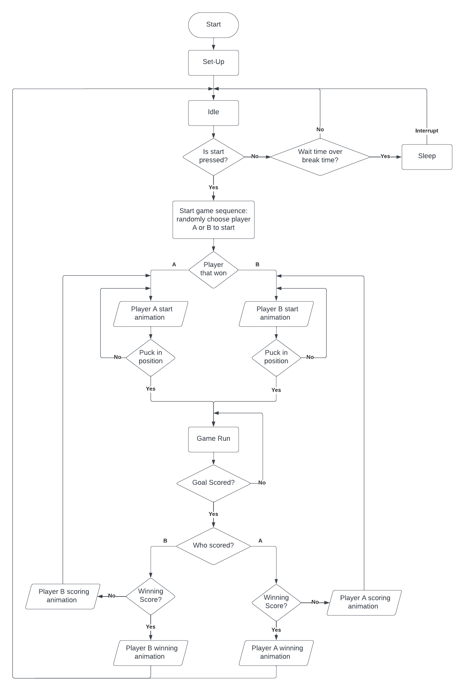 Caption: Flowchart of the system
Work on A5 - Component Analysis
I worked on the overview of the Component Analysis and the analysis of Puck Tracking Sensors. The document can be found here. Below is a table I made for my section.
| Method | Advantages | Disadvantages |
|---|---|---|
| IMU embedded inside puck | Direct tracking from the puck | Complexity, IMU errors, requires embedding a computer in the puck that can send position information to an external computer |
| Using a camera | Can potentially track multiple objects, common method for object tracking, simple to install | Requires more powerful external computing in order for it to be performant, weird edge cases |
| Grid of Hall effect sensors | Could integrate with the daughter boards that will hold the RGB LEDs, could use a basic algorithm that is performant | Requires meticulous placement of all sensors, potential interference from other components |
Update Project Description & PSDR
I also worked on finalizing the team’s PSDRs and updating the Project Description in the home of the team webpage. Here is a link to the pull request for the change. I made sure to make changes based on course staff feedback.
STM32 Tooling
Ben mentioned once in a meeting that VSCode had an STM32 extension. Me and Ben both run our machines on Linux, and in order to make sure that we are able to work efficiently, I did some exploratory work with the plugin. The extension info can be found below
Name: STM32 VS Code Extension
Id: STMicroelectronics.stm32-vscode-extension
Description: STM32 embedded development support added to Visual Studio Code.
Version: 1.0.0
Publisher: STMicroelectronics
VS Marketplace Link: https://marketplace.visualstudio.com/items?itemName=stmicroelectronics.stm32-vscode-extension
I was able to install and run all of the required tooling and the extension itself. Below are screenshots of STM32CubeMX running and our current project under firmware opened on the side.
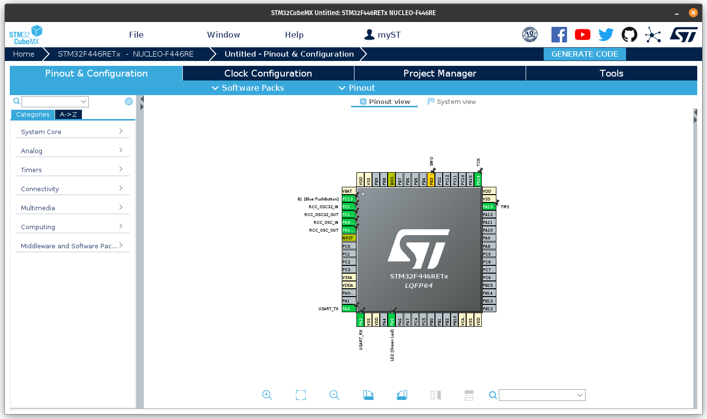 Caption: STM32CubeMX Running on PopOS!
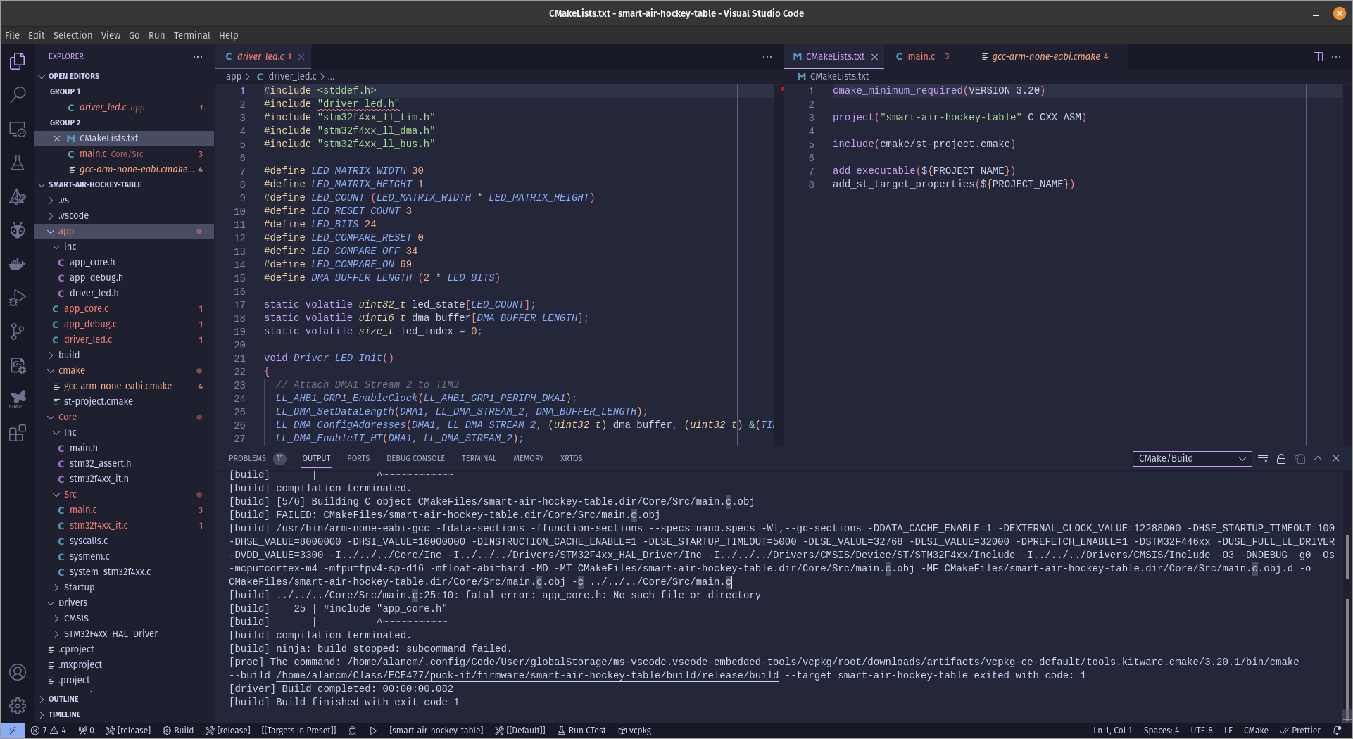 Caption:
 /firmware opened as an STM32 project in VSCode
However, there were some issues with building projects and the such.
Next Steps
The next two weeks will be focused on designing and building the table. Me and Will will be working together to get a proper design ready and start working with the Bechtel Innovation Design Center, where we will build the table. Will has begun building it on Fusion 360. I will be looking for ways of making table development easier since my laptop is not running Windows.
I will also be working on figuring out the tooling for VSCode and getting it working with our project and my teammates’ machines. This way, everyone will be able to take advantage of the newer programmer tooling available out there.
Week 3
Date: 2023-09-08
Week Hours: 18
Total Hours: 34
Description of Project Design Efforts
Over the past week, I was in charge of designing and building a new website for the team, the A3 - Software Overview report for the team, and continued prototyping with neopixel lights. I also contributed to some hardware prototyping and design discussions with the team.
Website
Most of my work was done creating the new website for the team. Early on, me and
Ben realized that it would be very tedious and inefficient for each member to
write in HTML for the progress reports. Therefore, I spent about 11 hours
(probably a bit more) on building a website from scratch that has all of the
same functionality as the previous website but with better user/write experience.
It was written from scratch using Astro for the web framework and tailwindcss for the styling. This was a combination I have used previously for my personal website www.alanchungma.com.
In order to maintain most of the features, I knew that I needed to provide the following sections in addition to a navigation bar I got here with various changes:
/ -> A Home page
/team/ -> Team page with profiles of all the members
/team/{MEMBERS} -> A subpage for each member which will house the progress report
/documents/ -> A page with all of the reports and other documents and files for the project
/references/ -> A page that holds all datasheets and references for the team
/media/ -> A page that will show pictures and videos for the team
/contact/ -> A page to reach out to the members
I will omit taking screenshots of the website, as you can view and interact
with the website here! A picture cannot show the neat hover effects.The source code of the website itself is available in the project repo.
Software Overview Project Report
I was tasked with writing the software overview for the team. This document can be accessed in the Documents page. Since the team has mostly been working on chosing and deciding on the hardware we will be working on, a lot of work was done in designing solutions and create a good software overview that covered as much ground as possible. Only a few things in the report have been discussed in passing, therefore, it took a good amount of time to get the whole document working. The main concern was the state diagram for the project, which can be viewed below.
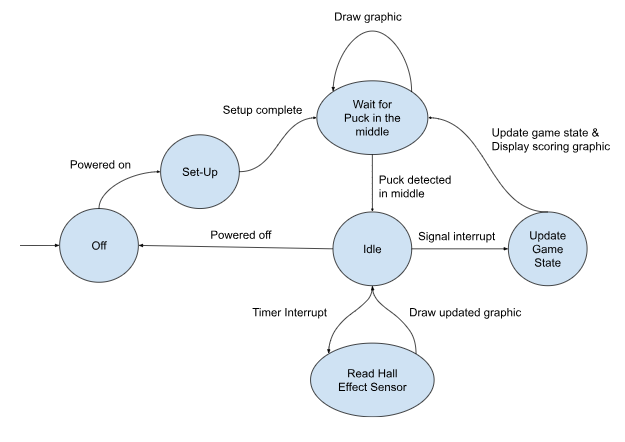 Caption: State diagram of the main microcontroller
I also created a flowchart that represents the game flow.
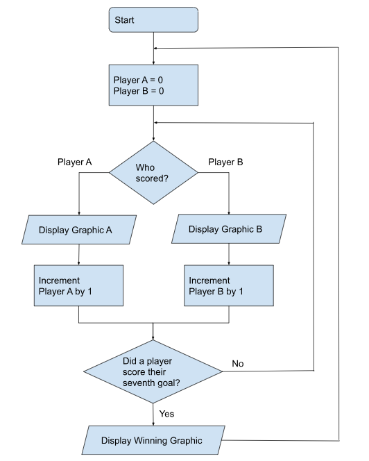 Caption: Flow chart for a typical game
Hardware Prototyping and Design Decisions
All that I did for Hardware Prototyping was getting the neopixel lights to work with a basic arduino script I made:
#include <Adafruit_NeoPixel.h>
#ifdef __AVR__
  #include <avr/power.h>
#endif
#define PIN        6
#define NUMPIXELS 30

Adafruit_NeoPixel pixels(NUMPIXELS, PIN, NEO_GRB + NEO_KHZ800);
#define DELAYVAL 500

void setup() {
#if defined(__AVR_ATtiny85__) && (F_CPU == 16000000)
  clock_prescale_set(clock_div_1);
#endif

  pixels.begin();
}

void loop() {
  pixels.clear();

  for(int i=0; i<NUMPIXELS; i++) {

    pixels.setPixelColor(i, pixels.Color(255, 255, 255));
    pixels.show();
    delay(DELAYVAL);
  }
}
Will picked up most of the prototyping work for the neopixels since I was working on the software overview.
Throughout the week, numerous discussions were had about the hardware. We ended up deciding to removing row master microcontrollers, and changing the number of LEDs on a daughter board to 4 instead of 9. The later decision was made because having the LEDs staggered in a 3x3 was very costly and would not not have netted the team better graphics since that relies on a less dense array of 2x2 hall effect sensors. Below is some ASCII art that displays this gap.
________________________
|                      |
|  L       L        L  |
|     H          H     |
|                      |
|                      |
|  L       L        L  |
|                      |
|     H          H     |
|  L       L        L  |
|                      |
________________________
As can be viewed from above, if you were to place two PCBs next to each other, there will be varying densities of lights between each hall effect sensor, where some gaps have only one light between each sensor while other gaps have two sensors between each gap.
We were also discussing the usage of a high-speed mux to multiplex all of the
hall effect sensors from a single master microcontroller. However, Ben and Trevor
came up with a much smarter solution of ORing each column and row and look at
the problem as a break-beam problem.
This idea was originally scratched since pushers would have blocked the beams,
but since this is done by the hall effect sensors and the puck should be the only
magnetic object on the table, it now works.
Below is an image Ben drew up showing this method of detecting the puck.
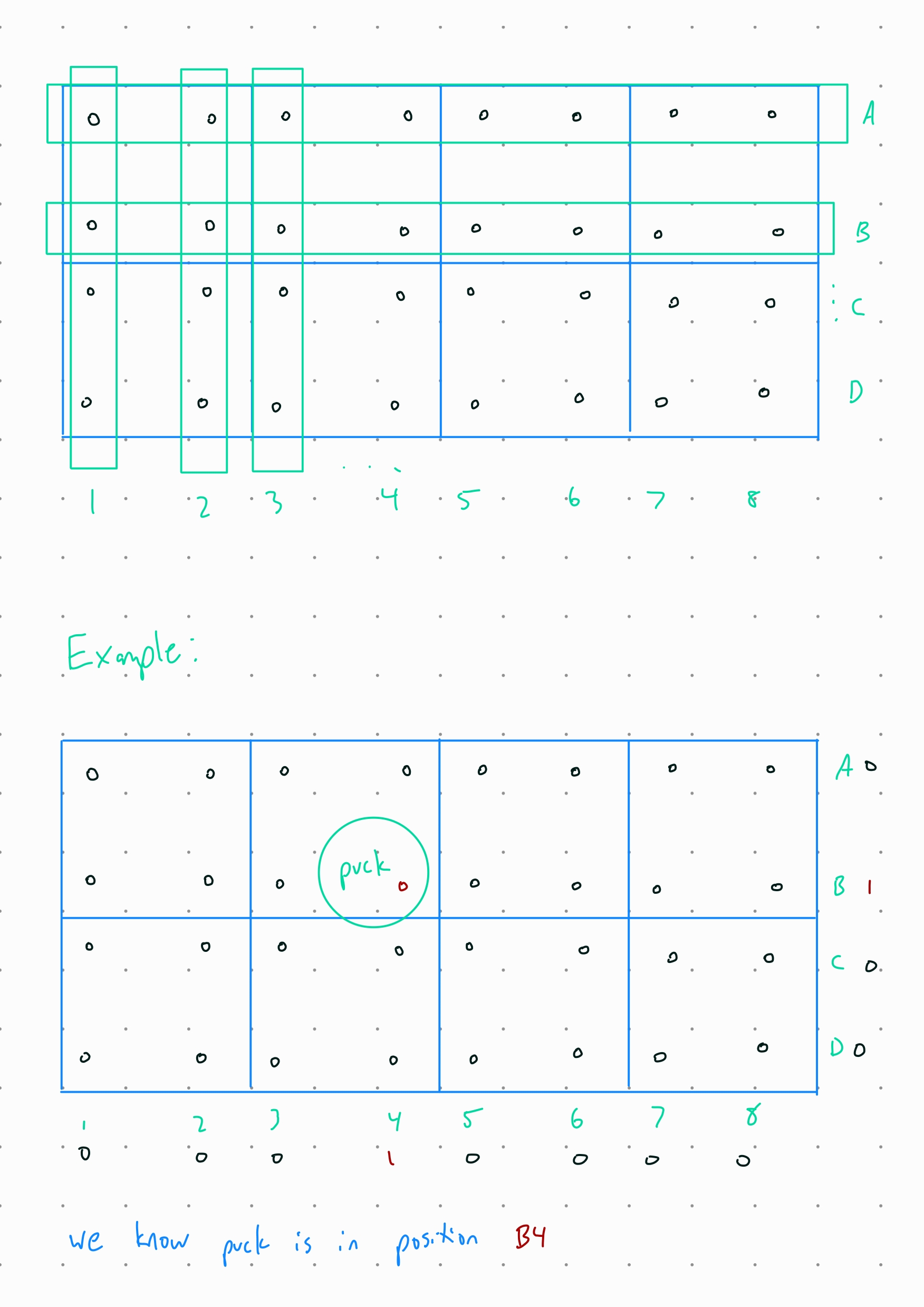 Caption: “Battleship” puck detection system
Week 1 & 2
Date: 2023-09-01
Week Hours: 16
Total Hours: 16
Description of Project Design Efforts
I have spent most of the past two weeks working on the design and technical specifications of the project. Most of this process was on a shared whiteboard in the lab. I also set up some of the infrastructure the team will be using for the remainder of the semester. I will be writing a lot of what has been discussed to the team’s documentation in PR over the weekend; diagrams will be added to the documentation as well.
First, I set up a repository which would hold all of the team’s source code and documentation; it can be found in the “SOURCE” button of the navigation bar above, or here. This will include technical documentation for our reference, microcontroller source code, and also a centralized version control for the website. The reason for the addition of the website to the repo was because the team encountered permission issues when attempting to access the destination over SSH. This is still the case as of 09/01/2023 10:18 am.
Second, I contributed extensively to the Final Project Proposal, which can be found under “Documents”. I wrote the project description, my corresponding team member section and wrote the first draft of our PSDRs. These PSDRs were then revised to align more closely to the course requirements, but each of their functionality remained the same.
Third, me and Ben discussed the feasibility and specifications of the table we will be constructing. The consensus was that building our own table will give us the most margin of error and the flexibility of changing the size and capabilities of the project at will. Another notable limitation of using a store-bought table was that taking it apart, modeling, and retrofiting the whole top would have taken more effort and felt out of scope of the project; using an off-the-shelf table would also pigeonhole the team to physical constraints that are unknown to us. We also decided that the interim playing surface dimensions will be of 1600mm x 800mm.
Fourth, me and Ben discussed the electronics layout of the components that will be under the playing surface. The array which will be on each daughter board that will sit under the surface will contain 4 Hall Effect sensors and 9 programmable LEDs; this is pending a feasibility test. These will be laid down in a 16x8 matrix under the playing surface, with a “row master” placed at the head of one row/column. Each row master will be connected to the master microcontroller, which will reside in its own PCB. Goal slot sensors will be connected directly to the main PCB, and an additional display will be attached to display supplemental information such as game score. The precense of a separate microcontroller in each daughter board is yet to be determined.
Fifth, me, Ben and Trevor discussed a possible algorithm to track the puck. A matrix of low precision (1-bit or 2-bit values) will be used to track the “weights” of each sensor. This will then be used to compute an estimated position by finding the average of all weights (a possible path of optimization is using SIMD instructions).
Sixth, I worked on the Functional Description and Theory of Operation of the Functional Specification, which can also be found in “Documents”.
Lastly, I had the chance to play with some LED lights I have. I was not able to get much progress, but I am planning to look into how the communication protocol is implemented and start building a library which the team will then use to control the lights.